Transcription of COOLING TOWERS - me.ua.edu
1 CHAPTER 39 COOLING TOWERS M OST air-conditioning systems and industrial processes gen- erate heat that must be removed and dissipated. Water is commonly used as a heat transfer medium heat from refrigerant condensers or industrial process heat exchangers. In the past, this was accomplished by drawing a continuous stream of water from a utility water supply or a natural body of water, heating it as it passed through the process, and then discharging the water directly to a sewer or returning it to the body of water.
2 Water pur- chased from utilities for this purpose has now become prohibitively expensive because of increased water supply and disposal costs. Similarly, COOLING water drawn from natural sources is relatively unavailable because the ecological disturbance caused by the increased temperature of discharge water has become unacceptable. Air-cooled heat exchangers cool water by rejecting heat directly to the atmosphere, but the first cost and fan energy consumption of these devices are high and the plan area required is relatively large.
3 They can economically cool water to within approximately 20 F of the ambient dry-bulb temperature-too high for the COOLING water requirements of most refrigeration systems and many industrial pro- cesses. COOLING TOWERS overcome most of these problems and therefore are commonly used to dissipate heat from water-cooled refrigera- tion, air-conditioning, and industrial process systems. The water consumption rate of a COOLING tower system is only about 5% of that of a once-through system, making it the least expensive system to operate with purchased water supplies.
4 Additionally, the amount of heated water discharged (blowdown) is very small, so the ecologi- cal effect is greatly reduced. Lastly, COOLING TOWERS can cool water to within 4 to 5 F of the ambient wet-bulb temperature, or about 35 F lower than can air-cooled systems of reasonable size. This lower temperature improves the efficiency of the overall system, thereby w reducing energy use significantly and increasing process output. Principle of Operation .. Application .. Design Conditions Performance Curves Types of COOLING TOWERS .
5 COOLING Tower Thermal Pevformance .. Materials of Construction .. COOLING Tower Theory .. Selection Considerations .. Tower Coeficients .. PRINCIPLE OF OPERATION A COOLING tower cools water by a combination of heat and mass transfer. Water to be cooled is distributed in the tower by spray noz- zles, splash bars, or film-type fill, which exposes a very large water surface area to atmospheric air. Atmospheric air is circulated by (1) fans, (2) convective currents, (3) natural wind currents, or (4) induc- tion effect from sprays.
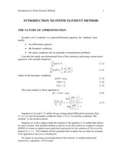
6 A portion of the water absorbs heat to change from a liquid to a vapor at constant pressure. This heat of vaporization at atmospheric pressure is transferred from the water remaining in the liquid state into the airstream. Figure 1 shows the temperature relationship between water and air as they pass through a counterflow COOLING tower. The curves indicate the drop in water temperature (A to B) and the rise in the air wet-bulb temperature (C to D) in their respective passages through the tower. The temperature difference between the water entering and leaving the COOLING tower (A minus B) is the range.
7 For a ' PERCENT DISTANCETHROUGH TOWER Fig. 1 Temperature Relationship Between Water and Air in Counterflow COOLING Tower steady-state system, the range is the same as the water temperature rise through the load heat exchanger, provided the flow rate through the COOLING tower and heat exchanger are the same. Accordingly, the range is determined by the heat load and water flow rate, not by the size or thermal capability of the COOLING tower. The difference between the leaving water temperature and enter- ing air wet-bulb temperature (B minus C) in Figure 1 is the approach to the wet bulb or simply the approach of the COOLING tower.
8 The approach is a fimction of COOLING tower capability, and a larger COOLING tower produces a closer approach (colder leaving water) for a given heat load, flow rate, and entering air condition. Thus, the amount of heat transferred to the atmosphere by the cool- ing tower is always equal to the heat load imposed on the tower, whereas the temperature level at which the heat is transferred is determined by the thermal capability of the COOLING tower and the entering air wet-bulb temperature. Thermal performance of a COOLING tower depends principally on the entering air wet-bulb temperature.
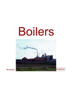
9 The entering air dry-bulb temperature and relative humidity, talcen independently, have an insignificant effect on thermal verformance of mechanical-draft " COOLING TOWERS , but do affect the rate of water evaporation in the COOLING tower. A psychromehic analysis of the air passing through a COOLING tower illustrates this effect (Figure 2). Air enters at the ambient condition Point A, absorbs heat and mass (moisture) from the water. and exits at Point B in a saturated condition (at verv light d " loads, the discharge air may not be fully saturated).
10 The amount of The preparation of this chapter is assigned to TC , Coollng TOWERS and heat transferred from the water to the air is proportional to the dif- Evaporative Condensers. ference in enthalpy of the air between the entering and leaving 2008 ASHRAE Handbook-HVAC Systems and Equipment conditions (hB - hA). Because lines of constant enthalpy correspond almost exactly to lines of constant wet-bulb temperature, the change in enthalpy of the air may be determined by the change in wet-bulb temperature of the air.