Transcription of Coping with the Risk of Board Flexure Damage to Multilayer ...
1 [5](click to enlarge) [5] Multilayer ceramic capacitors are susceptible to Board Flexure failures. Published on Medical Electronics Design ( )Home > Coping with the Risk of Board Flexure Damage to Multilayer Ceramic CapacitorsCoping with the Risk of Board Flexure Damage to Multilayer Ceramic CapacitorsPatrick Gormally, John Bultitude, and Vito CoppolaCreated 2007-10-01 02:00[1] Coping with the Risk of Board Flexure Damage to Multilayer Ceramic Capacitors [2]October 01, 2007 By: Patrick Gormally, John Bultitude, and Vito Coppola [3] Find more content on: Components [4]Techniques are emerging to minimize the incidence of a PCB component defect that can cause problems in devices in the of Multilayer ceramic capacitors (MLCCs) caused by printed circuit Board (PCB)
2 Flexure have received considerable attention recently, not only because of product reliability concerns, but also because there is no screening method available for detecting cracked capacitors after they are assembled onto circuit Flexure control is especially important in medical applications because of the potential for serious failures resulting from high-current shorting to affect components surrounding the failed the number of MLCCs per application increases, Board - Flexure MLCC cracking may translate into an unacceptably high field failure rate for medical devices. Further, subcontractors that process PCB assemblies for multiple customers are increasingly involved in equipment manufacture. Such involvement may make this issue more serious than it would be if OEM production lines were developed specifically to manufacture one particular OEM , flex-cracking problems with MLCCs have led to Board -handling process improvements at OEM and subcontracting establishments, to tests for capacitor resistance to flex cracking, and to improved design standards for circuit boards.
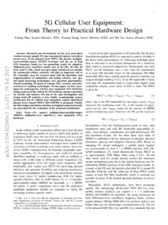
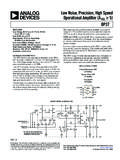
3 Nonetheless, cracking remains a predominant failure mode for these capacitors. The failures usually start as leakage failures and a loss in insulation resistance (IR) or in capacitance. Flexure Damage readily appears in large-case-size MLCCs. It is much less obvious in small-case-size MLCCs located in possibly Flexure -sensitive areas of the 1 of 7 Coping with the Risk of Board Flexure Damage to Multilayer Ceramic Capacitors3/11/2011 [6]Figure 1. (click to enlarge) [6]Stresses from Board flexing due to process handling are transmitted to the capacitor termination and underlying ceramic. [7]Figure 2. (click to enlarge) [7]The cross section of an MLCC (left) reveals a typical Board Flexure crack in the corner of the MLCC. The diagram on the right shows electrode layers in an MLCC and indiccates where tension forces form the manufacturers have made capacitor improvements that mitigate cracking problems caused by Board Flexure , developing three different approaches to addressing this failure mode in MLCCs.
4 One is open-mode designs. In this case, the MLCC is designed so that any Board -flex cracking does not penetrate the active electrode area so as to cause IR loss and shorting. Alternatively, the use of polymer terminations allows greater Flexure before cracking occurs, and the cracking does not result in IR loss or short circuits. The third approach involves optimizing solder land design on the circuit Board , which is another way of minimizing the stress level during and CrackingWhen a circuit Board is deflected, it forms an arc. The outer surface of the solder pads and the end of the terminated soldered capacitor chip move apart. This in turn places the capacitor chip in ceramic capacitors are soldered to a circuit Board and the Board is bent, forces are transmitted through the solder to the capacitor termination and to the ceramic material just under the termination.
5 These forces are not pure tensile forces; there may be some torque involved during Board Flexure , and the forces are modified also by the amount and shape of the solder fillet. However, two general types of cracking occur: cracking produced by primarily tensile forces, and cracking produced by primarily compressive forces. Both types of force can cause cracking under the MLCC terminations, but, for the most part, ceramic materials such as those used for MLCCs are more susceptible to tensile-type generated by Flexure are found usually on the bottom surface of the MLCC, under the termination where the part is mounted to the PCB (see Figure 1). They are rarely found on the top of the part. When the applied flexural forces exceed the strength of the ceramic, a crack forms from the edge of the termination and moves toward the chip capacitors are made of fine grains of ceramic material that are diffusion-bonded during firing.
6 The ceramic structure resulting from the production process makes for a very brittle material. Ceramics have great strength under compression but fail easily in tension or in shear. Under tensile or shearing stress, they sustain brittle fractures. The result is a typical crack pattern that will vary with the manner in which the forces are applied (see Figure 2).Because of variability in the size of capacitors and the solder fillet shape, tensile cracks can completely sever the termination end from the rest of capacitor in some cases, or they may simply break a corner off the capacitor. The capacitor remains held together by termination material in the latter case. In both cases, the cracks allow ingress of humidity and contaminants that will ultimately cause MLCC for Reducing Board FlexurePCB manufacturers use proven design standards for circuit Board pad layout and component location in order to mitigate Board Flexure .
7 These usually require a 5-mm space between a Board 's edge and a ceramic capacitor. Standards also typically indicate the orientation of the mounted capacitor relative to the Board edge parallel to the edge is usually better and they call for routed reliefs along the Board parting lines to reduce stress during the depaneling process. Manual bending of boards to depanel, as well as other methods that permit flexing of the boards, such as scoring and wheel cutting, have been eliminated in favor of punching and routing. The latter processes, combined with routed reliefs along most of the parting lines, are used in a variety of high-reliability medical electronic assembly 2 of 7 Coping with the Risk of Board Flexure Damage to Multilayer Ceramic Capacitors3/11/2011 [8]Figure 3.
8 (click to enlarge) [8]A Board layout in which the solder lands for mounted MLCCs are kept small is best for discouraging capacitor cracking. [9]In addition, control of solder lands can help reduce the forces that crack ceramic capacitors by minimizing the exposed surfaces (see Figure 3). This is not a total cure, but it is an area to consider when designing ceramic capacitors into circuit Board and soldering Measurement and TestingThe Japanese industrial standard JIS C 5101-1, published in 1998, contains standards for measuring flex-cracking resistance in MLCCs and a description of methodology. (A similar process is published in IEC 60384-1, the analogous European standard of the International Electrotechnical Commission.)Data from controlled flex testing conducted in accordance with the JIS C 5101-1 standard have provided a method of evaluating the Flexure strength of a particular MLCC design.
9 They have also been predictors of the effect of customers' production processes. Most manufacturers using MLCCs have established a limit for Board Flexure and often specify the allowable amount of Flexure in their MLCC product JIS C 5101-1 standard establishes the maximum permissible Board flex across a 90-mm span as 2 mm. This 2-mm Flexure limit accommodates most MLCC customers' specifications and most MLCC manufacturers' capabilities. The standard's 2-mm allowance also has a requirement component in that capacitors must not fail due to Flexure of the Board up to the specified measures can be taken to determine where in the OEM or subcontractor manufacturing process Board Flexure could be a problem. This involves evaluating each process in which the populated PCB is handled to discover occasions of potentially excessive Board develop a baseline of data, as well as provide actual measurement data for further evaluation, each manufacturing process that could subject the populated PCB to tension should be tested on the production line.
10 Strain gauges are effective measurement devices that can be tests that can be run involve installing miniature strain gauges at or very near the capacitor site and running the boards through the production process while recording strain. Such miniature instruments are available and have been used to perform many evaluations of strain levels at various Board locations on PCBs that contain MLCCs that were intended for incorporation into medical electronic equation for converting Board flex in millimeters into strain ( ) in terms of microstrain ( ) applied to the Board iswhere T is the Board thickness, L is the span between supports, and is the Board Flexure , all as measured in Board Flexure testing was performed on open-mode-design capacitors soldered onto epoxy resin boards.