Transcription of Coriolis X - ABB Ltd
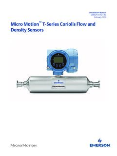
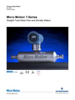
1 Application Sheet2102772-AACoriolis XSeries InterfaceCORIOLIS XSERIES INTERFACEThe ABB Totalflow XSeries Coriolis application allows an XSeries device (XFC or XRC) to interface with an Emerson micro motion Coriolis transmitter and perform volume and corrected mass calculations. Mass flow output from the Coriolis device, retrieved via Modbus protocol, is requested and utilized by the interface application to calculate corrected volume. Daily logs, hourly logs, characteristics and event logs are collectable, both locally and remotely, from the Coriolis application s historical data ( corrected volume, corrected mass, uncorrected mass, energy, and alarms).
2 PCCU (local PC user Configuration and Collection software) provides the user interface to the Totalflow XSeries device for configuration, calibration, collection and viewing of historical data, as well as the ability to view and edit parameters resident in the micro motion Coriolis transmitter. The Coriolis Interface allows the user to enter the calibration pressure (PCal) and pressure effect (PEffect), which are then applied to mass flow to produce the corrected mass flow. A list of configurable parameters is shown on the back. SOFTWARE REQUIREMENTS1. XFC flash or XRC flash with micro motion Coriolis support features2.
3 PCCU32 version WinCCU version Appropriate XFC or XRC Configuration FilesABB Products7051 Industrial , OK 74006 Tel: (918) 338-4888 Fax: (918) 338-4699 (800) 442-3097 For more information, please contact your local ABB Totalflow representative or visit our XSeries InterfaceXSERIES/ Coriolis INTERFACE CONFIGURATIONEach XSeries/ Coriolis interface uses one XSeries measurement tube application. The measurement tube can be forward, reverse, or bi-directional. For two forward tube applications, two Coriolis interfaces are required. An XSeries G3 device can support a maximum of either one bi-directional interface or two single direction flow TRANSMITTER CON- FIGURATION PARAMETERSMany of the micro motion transmitter parameters may be configured using Totalflow s PCCU or newer MMI software.
4 Below are some of the micro motion Curved Tube Coriolis configuration parameters that may be read from or written to the micro motion transmitter using the Totalflow Coriolis interface and PCCU Flow Correction ParametersCalibration Pressure (PCal) R/WPressure Effect (PEffect) R/WMass Flow ParametersDamping Period R/WFlow Temperature Coefficient (FT) R/WLow Flow Cutoff (lbm/s) R/WMeter Factor R/WFlow Calibration Factor (FCF) R/WMechanical Zero R onlyDensity ParametersMeasured Density from Coriolis R onlyFlowing Density Factor (FD) R/WDamping Period R/WTemperature Coefficient (DTC) R/WLow Density Cutoff R/WLow Density Calibration (D1) R/WSlug Duration R/WTemperature Corrected Tube Period (K1) R/WHigh Slug Limit R/WHigh Density Calibration (D2) R/WLow Slug Limit R/WTemperature Corrected Tube Period (K2) R/WDensity Meter Factor R/WTemperature ParametersDamping Period R/WCalibration Offset R/WCalibration Slope R/WExternal Temperature R/WT- series ParametersTemperature Corrected Tube Period (K3) R/WFFQ R/WTemperature Corrected Tube Period (K4) R/WDTG R/WDensity Calibration (D3)
5 R/WDFQ1 R/WDensity Calibration (D4) R/WDFQ2 R/WFTG R/WNote: Straight tube (T- series ) parameters are also = Read R/W = Read/Writ
