Transcription of COURSE OBJECTIVES CHAPTER 4 4. STABILITY
1 I COURSE OBJECTIVES CHAPTER 4 4. STABILITY 1. Explain the concepts of righting arm and righting moment and show these concepts on a sectional vector diagram of the ship s hull that is being heeled over by an external couple. 2. Calculate the righting moment of a ship given the magnitude of the righting arm. 3. Read, interpret, and sketch a Curve of Intact Statical STABILITY (or Righting Arm Curve) and draw the sectional vector diagram of forces that corresponds to any point along the curve. 4. Discuss what tenderness and stiffness mean with respect to naval engineering. 5. Evaluate the STABILITY of a ship in terms of: a. Range of STABILITY b. Dynamic STABILITY c. Maximum Righting Arm d. Maximum Righting Moment e.
2 Angle at which Maximum Righting Moment Occurs 6. Create a Curve of Intact Statical STABILITY for a ship at a given displacement and assumed vertical center of gravity, using the Cross Curves of STABILITY . 7. Correct a GZ curve for a shift of the ship's vertical center of gravity and interpret the curve. Draw the appropriate sectional vector diagram and use this diagram to show the derivation of the sine correction. 8. Correct a GZ curve for a shift of the ship's transverse center of gravity and interpret the curve. Draw the appropriate sectional vector diagram and use this diagram to show the derivation of the cosine correction. 9. Determine the initial slope of the GZ curve using Metacentric Height. 10. Analyze and discuss damage to ships, including: a.
3 Use added weight method to calculate ship trim, angle of list and draft b. Qualitatively discuss lost buoyancy method c. Navy Damage STABILITY Criteria for ships ii 11. Analyze and discuss free surface effects, including: a. Consequences of free surface on overall ship STABILITY b. Ways to limit the effects of free surface c. Calculate the effective metacentric height d. The meaning of a negative metacentric height and show this condition on a sectional vector diagram of the ship s hull. e. Correct the GZ curve 4 - 1 Introduction In the last CHAPTER we studied hydrostatics of a displacement ship. In that CHAPTER there were only two internally produced forces and no external forces were considered.
4 The resultant buoyant force and the resultant weight of the ship were in vertical alignment so that no moments were produced. The criteria for static equilibrium were met so that the displacement ship would forever sit motionless until external forces acted on the ship or a weight change occurred. In this CHAPTER we are concerned with the ability of the ship to remain upright when external forces are trying to roll it over. We are mostly concerned with the transverse movement or heeling because it is nearly impossible to tip a ship end to end (longitudinally). Here the resultant weight of the ship is very often not in vertical alignment with the resultant buoyant force so that internal moments are produced. First, we will study the general principle of a righting moment for a ship.
5 We will see how the magnitude of the righting moment is a function of the heeling angle. Second, we will show how the righting moment is affected by changes in the vertical and transverse location of the center of gravity of the ship. Third, we will discuss how STABILITY is affected by hull damage and learn ways to model a damaged ship. Fourth, we will study the effects of free surface (fluids in less than full tanks or compartments) on the righting moment. Finally, we will show the effects of a negative metacentric height on the STABILITY of ship. 4 - 2 The Internal Righting Moment Produced by a Heeling Ship Understanding overall STABILITY comes down to understanding how the relative positions of the resultant weight of the ship and the resultant buoyant force change when a ship is heeled over by an external moment or couple.
6 The External Couple The external couple can be caused by the action of wind pushing on one side of the ship, trying to translate the ship in that direction, and the water pushing back on the hull in the opposite direction. The resultant forces from these two distributed forces would be acting parallel to the water s surface. The resultant wind force would be above the water and the resultant water force would be below the water. Thus the two resultant forces would not be aligned. They would form an external couple or moment causing the ship to rotate. A good analogy can be made by picturing a steering wheel -- the wind is pushing at the top of the steering wheel and the water is pushing in the opposite direction at the bottom.
7 The steering wheel will rotate when acted upon by these unbalanced forces. Refer to Figure The Internal Couple A ship will also tend to rotate when acted upon by wind and water. However, as the ship heels over due to an external moment it also develops an internal moment. The internal moment acts in response to the external moment and in the opposite rotational direction. If the internal and external moments balance the ship will stay heeled at that angle of inclination, otherwise it will keep heeling until the ship capsizes. To understand how the ship develops an internal moment, consider how the relative positions of the resultant weight of the ship and the resultant buoyant force change as the ship is heeled over.
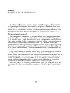
8 The resultant weight of the ship acts vertically downward at the center of gravity. Only changes in the distribution of weight affect the location of the center of gravity. If no weight changes occur then no shifts in the center of gravity will occur. The resultant buoyant force acts vertically upward at the center of buoyancy. The center of buoyancy is located at the centroid of the underwater volume of the ship. When the ship is heeled over by an external moment the underwater shape changes and thus the centroid moves. Where the center of buoyancy moves with respect to the center of gravity defines the STABILITY characteristics of the ship as the ship is heeled over. Figure shows the sectional view of a ship that is being heeled over due to an external moment.
9 It shows the relative positions of the center of gravity and center of buoyancy for a ship that has been designed properly. Notice the perpendicular distance between the lines of action of the resultant weight and resultant buoyant force. This distance is the righting arm (GZ). 4 - 3 Figure Heeled Ship due to an External Moment You should be able to draw Figure without the use of your notes. To find the internal righting moment multiply the righting arm by the magnitude of the resultant weight of the ship (or the magnitude of the resultant buoyant force since the magnitude of these forces are equal). The equation below shows this relationship. BFGZGZRM= = where: RM is the internal righting moment of the ship (LT-ft) S is the displacement of the ship (LT) FB is the magnitude of the resultant buoyant force (LT) GZ is the righting arm (ft) which is the perpendicular distance between the line of action of the resultant buoyant force and the resultant weight of the ship.
10 This distance is a function of the heeling angle. Water Resistance WLf BF G Z B WLo MT External Upsetting Force C L ! 4 - 4 The Curve of Intact Statical STABILITY Figure is only a snapshot of the total STABILITY picture. We are really interested in how Figure changes as the ship is heeled over from zero degrees to large enough angles of heel to make the ship capsize. To help us conceptualize this process, a graph of heeling angle (degrees) versus righting arm (GZ) is constructed. This graph is called the curve of intact statical STABILITY or the Righting Arm Curve . The curve of intact statical STABILITY assumes the ship is being heeled over quasi-statically in calm water. Quasi-static means that the external moment heeling the ship over is doing so in infinitely small steps so that equilibrium is always present.