Transcription of cp2102rev1 0 - SparkFun Electronics
1 Rev. 10/04 Copyright 2004 by Silicon LaboratoriesCP2102CP2102 SINGLE-CHIP USB TO UART BRIDGES ingle-Chip USB to UART Data Transferz Integrated USB transceiver; no external resistors requiredz Integrated clock; no external crystal requiredz Integrated 1024-Byte EEPROM for vendor ID, product ID, serial number, power descriptor, release number, and product description stringsz On-chip power-on reset circuitz On-chip voltage regulator: V outputz 100% pin and software compatible with CP2101 USB Function Controllerz USB Specification compliant; full-speed (12 Mbps)z USB suspend states supported via SUSPEND pinsAsynchronous Serial Data BUS (UART)z All handshaking and modem interface signalsz Data formats supported: - Data bits: 5, 6, 7, and 8- Stop bits: 1, , and 2- Parity: odd, even, mark, space, no parityz Baud rates: 300 bps to 1 Mbitsz 576 Byte receive buffer.
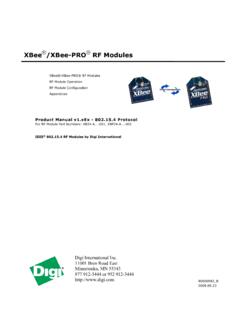
2 640 byte transmit bufferz Hardware or X-On/X-Off handshaking supportedz Event character support z Line break transmissionVirtual COM Port Device Driversz Works with existing COM Port PC applicationsz Royalty-free distribution licensez Windows 98 SE/2000/XPz MAC OS-9z MAC OS-Xz Linux and greaterUSBX press Direct Driver SupportExample Applicationsz Upgrade of RS-232 legacy devices to USBz Cellular phone USB interface cablez PDA USB interface cablez USB to RS-232 serial adapterSupply Voltagez Self-powered: to Vz USB bus powered: to VPackagez Lead free 28-pin MLP (5 x 5 mm)Ordering Part Numberz CP2102-GMTemperature Range: 40 to +85 CFigure 1. Example System VVoltageRegulator48 MHz OscillatorINOUTSUSPENDSUSPEND1112 REGIN7 GND3 RST9D+4D-58 UARTRIDCDCTSRTSRXDTXDDSRDTR2128272625242 323 External RS-232 transceiver or UART circuitry(to external circuitry for USB suspend states)VBUSD-D+GND456 USB CONNECTOR61 VDDVBUSUSB FunctionControllerUSBT ransceiver640B TX Buffer576B RX Buffer1024B EEPROMVDDD1 D2 D3CP21022 Rev.
3 OF CONTENTSS ectionPage1. System Overview .. 42. Absolute Maximum Ratings .. 53. Global DC Electrical Characteristics .. 54. Pinout and Package Definitions .. 65. USB Function Controller and Transceiver .. 116. Asynchronous Serial Data Bus (UART) Interface .. 127. Internal EEPROM .. 128. Virtual Com Port Device Drivers .. 139. USBX press Direct Driver Support .. 1310. Voltage Regulator .. 13 Contact Information .. 16CP21024 Rev. System OverviewThe CP2102 is a highly-integrated USB-to-UART Bridge Controller providing a simple solution for updating RS-232designs to USB using a minimum of components and PCB space. The CP2102 includes a USB full-speedfunction controller, USB transceiver, oscillator, EEPROM, and asynchronous serial data bus (UART) with fullmodem control signals in a compact 5 x 5 mm MLP-28 package.
4 No other external USB components are on-chip EEPROM may be used to customize the USB Vendor ID, Product ID, Product Description String,Power Descriptor, Device Release Number, and Device Serial Number as desired for OEM applications. TheEEPROM is programmed on-board via the USB allowing the programming step to be easily integrated into theproduct manufacturing and testing Virtual COM Port (VCP) device drivers provided by Silicon Laboratories allow a CP2102-basedproduct to appear as a COM port to PC applications. The CP2102 UART interface implements all RS-232 signals,including control and handshaking signals, so existing system firmware does not need to be modified.
5 In manyexisting RS-232 designs, all that is required to update the design from RS-232 to USB is to replace the RS-232level-translator with the evaluation kit for the CP2102 (Part Number: CP2102EK) is available. It includes a CP2102-based USB-to-UART/RS-232 evaluation board, a complete set of VCP device drivers, USB and RS-232 cables, and fulldocumentation. Contact a Silicon Labs sales representatives or go to to order the CP2102 Evaluation Absolute Maximum Ratings3. Global DC Electrical CharacteristicsTable 1. Absolute Maximum RatingsParameterConditionsMinTypMaxUnits Ambient temperature under bias 55 125 CStorage Temperature 65 150 CVoltage on any I/O Pin or RST with respect to GND on VDD with respect to GND Total current through VDD and GND 500mAMaximum output current sunk by RST or any I/O pin 100mANote:Stresses above those listed may cause permanent damage to the device.
6 This is a stress rating only, and functional operation of the devices at or exceeding the conditions in the operation listings of this specification is not implied. Exposure to maximum rating conditions for extended periods may affect device 2. Global DC Electrical CharacteristicsVDD= to V, 40 to +85 C unless otherwise CurrentVDD= V 26 mASupply Current in SuspendVDD= V 330 ASpecified Operating Temperature Range 40 +85 CTable 3. UART and Suspend I/O DC Electrical CharacteristicsVDD= to V, 40 to +85 C unless otherwise High VoltageIOH= 3mAIOH= 10 AIOH= 10mAVDD VDD VOutput Low VoltageIOL= AIOL=25mA VInput High VInput Low Voltage Leakage Current 2550 ACP21026 Rev. Pinout and Package DefinitionsTable 4.
7 CP2102 Pin DefinitionsNamePin #TypeDescriptionVDD6 Power InPower V Power Supply Voltage V Voltage Regulator Output. See <PDF link>Section I/ODevice Reset. Open-drain output of internal POR or VDD monitor. An external source can initiate a system reset by driving this pin low for at least 15 In5 V Regulator Input. This pin is the input to the on-chip voltage reg-ulator. VBUS8D InVBUS Sense Input. This pin should be connected to the VBUS sig-nal of a USB network. A 5 V signal on this pin indicates a USB net-work +4D I/OUSB D+D 5D I/OUSB D TXD26D OutAsynchronous data output (UART Transmit)RXD25D InAsynchronous data input (UART Receive)CTS23*D InClear To Send control input (active low)RTS24*D OutReady to Send control output (active low)DSR27*D inData Set Ready control input (active low)DTR28*D OutData Terminal Ready control output (active low)DCD1*D InData Carrier Detect control input (active low)RI2*D InRing Indicator control input (active low)SUSPEND12*D OutThis pin is driven high when the CP2102 enters the USB suspend *D OutThis pin is driven low when the CP2102 enters the USB suspend , 13 22 These pins should be left unconnected or tied to VDD.
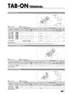
8 *Note: Pins can be left unconnected when not 2. MLP-28 Pinout Diagram (Top View)45672131112131498101817161520211925 262728232224CP2102 Top ViewDCDRIGNDD+D-VDDREGINVBUSRSTNCSUSPEND SUSPENDNCNCNCNCNCNCNCNCNCNCCTSRTSRXDTXDD SRDTRGNDGNDCP21028 Rev. 3. MLP-28 Package DrawingTable 5. MLP-28 Package 28 ND 7 NE 7 AA BB CC DD 1 EDA2AA1eA3E2 ReLBottom ViewSide View234567891012131421201917161528272624 2322E2252D21118D226 x e6 x eDETAIL 1 DETAIL 1 AABBCCDDbCP2102 Rev. 4. Typical MLP-28 Landing DiagramOptional GND mmTop mmCP210210 Rev. 5. Typical MLP-28 Solder Paste mmTop mmCP2102 Rev. USB Function Controller and TransceiverThe Universal Serial Bus function controller in the CP2102 is a USB compliant full-speed device with integratedtransceiver and on-chip matching and pull-up resistors.
9 The USB function controller manages all data transfersbetween the USB and the UART as well as command requests generated by the USB host controller andcommands for controlling the function of the UART. The USB Suspend and Resume signals are supported for power management of both the CP2102 device as wellas external circuitry. The CP2102 will enter Suspend mode when Suspend signaling is detected on the bus. Onentering Suspend mode, the CP2102 asserts the SUSPEND and SUSPEND signals. SUSPEND and SUSPENDare also asserted after a CP2102 reset until device configuration during USB Enumeration is CP2102 exits the Suspend mode when any of the following occur: (1) Resume signaling is detected orgenerated, (2) a USB Reset signal is detected, or (3) a device reset occurs.
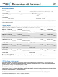
10 On exit of Suspend mode, theSUSPEND and SUSPEND signals are SUSPEND and SUSPEND temporarily float high during a CP2102 reset. If this behavior is undesirable, astrong pulldown (10 k ) can be used to ensure SUSPEND remains low during reset. See Figure 6 for otherrecommended 6. Typical Connection DiagramOption 1: A k pull-up resistor can be added to increase noise 2: A F tantalum capacitor can be added if powering other devices from the on-chip 3: Avalanche transient voltage suppression diodes should be added for ESD protection. Option 3: Use Littlefuse p/n SP0503 BAHT or 4: 10 k resistor to ground to hold SUSPEND low on initial power on or device + FC11 FRIDCDCTSRTSRXDTXDDSRDTR2128272625242323 External RS-232 transceiver or UART circuitry(to external circuitry for USB suspend states)VBUSD-D+GND456 USB k D1D2D3 Option 1R210 k Option 4 Option FTANTO ption 2CP210212 Rev.