Transcription of CRACK DETECTION METHODS USING RADIO …
1 The 14th World Conference on Earthquake Engineering October 12-17, 2008, Beijing, China CRACK DETECTION METHODS USING RADIO frequency identification AND electrically conductive MATERIALS Koichi Morita1 and Kazuya Noguchi2 1 Senior Research Engineer, Building Research Institute, Tsukuba, Japan, 2 Researcher , National Institute for Land and Infrastructure Management, Tsukuba, Japan ABSTRACT : RADIO frequency identification (RFID) tag is a promising device for the management of products at a very lowcost. Huge number of such low-cost sensors can be installed to the structure beforehand, after a disaster we can access to these sensors wirelessly and very easily. In this system, a printed sheet is applied to a part of structure in which CRACK will occur. Copper wire is connected to the attachment on the structure and a RFID tag. When a CRACK occurs, the printed sheet is broken, resulting in an increase in resistance.
2 CRACK width can be estimated bythe ability of an RFID transmitter to communicate with the tag. By fatigue test of steel specimen with a notch,the relationships between CRACK width and conductivity of the materials are examined. It is shown that the levelof CRACK width can be related to the ability of the printed sheet to conduct electricity or not. Very small steel CRACK can be detected by this sensor. KEYWORDS: Keywords: CRACK DETECTION , electrically conductive Paint, Health Monitoring,RFID-tag, 1. INTRODUCTION In recent years, much attention has been given to structural health monitoring technology to diagnose thecondition of structures USING a sensor attached to them, and the number of research projects on the healthmonitoring of architectural structures is on the rise. If we have to reduce life cycle costs of a building from construction to maintenance, it is very effective tomonitor structural health of a building.
3 Most buildings built during 1970 s construction rush in Japan seem torapidly deteriorate, and it is necessary to establish structural health estimation of these buildings. In 2002,performance certification mark system of existing housings is started in Japan, and structural performance willbe displayed by visual inspection and structural design data, etc. However, in this performance evaluation,measurement such as acceleration is not carried out because of technical difficulties. The decisions from the inspection by experts according to manuals tend to be judged to safe side. It is important to carry outmeasurement to evaluate damages objectively and quantitatively. Damage DETECTION and health monitoring are classified into two METHODS . The first method is based on vibration measurement, and the other one is based on phenomena such as cracking or heat.
4 Each method has its strongpoints and its weak points. A damage identification system based on vibration measurements is effective for damage DETECTION of whole structures or the story of a structure but it is not effective for damage DETECTION of aspecific portion of a building such as its structural members. On the other hand, damage DETECTION based onphenomena such as cracking or heat is effective for damage DETECTION of a specific portion of a building such asits structural members. By combining these two METHODS , it becomes possible to monitor structural healthprecisely. A damage identification system based on vibration measurements has a possibility to find out the process of damage, but in such system, maintenance of sensor and data acquisition system costs very much. In some cases,it is not economical to measure for all time. It is very difficult to install such data acquisition system to many buildings because of high costs.
5 On the other hand, the techniques which grasp the local damage by use off-line system(Wood, and Neikirk, (2001)), such as carbon fiber lattice sensor or maximum value memory sensor are much more economical than vibration measurement system. In this study, CRACK DETECTION sensor USING RADIO frequency identification (RFID) tag and electrically conductive paint and printed sheets is proposed because of its low costs and easinessThe 14th World Conference on Earthquake Engineering October 12-17, 2008, Beijing, China of the measurement. The RFID tag is generally used for distinction or management of human or products. Byusing this RFID tag and transmitter, RADIO communication is possible. In buildings that were damaged by the Great Hanshin-Awaji Earthquake, the examination of steel structures covered with fire-resistant material required considerable effort, including removal of the material to detectcracks and breakdowns that occurred at the end of steel beams and in other parts of the buildings, and it wasextremely difficult to investigate the inside of fire-resistant materials.
6 (The Great Hanshin-Awaji Earthquake Investigative Report Editorial Committee (1997)) Such types of damage should be examined carefully becausethey are highly likely to lead to the breakdown of beam ends and other parts of the building in the event of a large earthquake. In this study, fundamental experiments for the relationship between CRACK width and the resistance ofelectrically conductive materials are carried out, and possibility of application of this technique is examined. 2. OUTLINE OF SYSTEM RADIO frequency identification (RFID) By the RADIO communication between RFID tag and transmitter with antenna and controller, the object can berecognized. Distance of this communication depends on the type of transmitter and tag. At the present time, there are RFID products whose communication distance is 2[cm] to 9[m]. It is possible to communicate with amyriad tag by one transmitter because of the mobility of the transmitter.
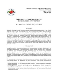
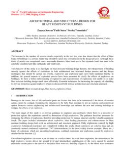
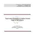
7 The price of tag itself is much more economical than conventional sensors. As shown in Figure 1, JB-1000 RFID tags (Japan Information System Co., Ltd.) were used in this study, andrelatively low-priced tags of frequency and a long reading distance were chosen. These tags are readable and rewritable, and their maximum reading distance is 130 cm. The tags mentioned above are commercially available, but in this study, RFID tags with a tamper switch wereprepared. The tags were read USING the antenna and the scanner shown in Figure 2, as well as a notebook personal computer. Figure1 : RFID-tag Figure 2 : Antenna and Scanner The 14th World Conference on Earthquake Engineering October 12-17, 2008, Beijing, China CRACK DETECTION System Figure 3 shows an outline of the CRACK DETECTION system USING an RFID tag with a tamper switch.
8 Thereader/writer can read the ID number of the RFID tag with a tamper switch connected to a DETECTION sheet anddetermine whether the connected switch is on or off. The reader/writer determines that the switch is off if thelead wire on the DETECTION sheet is broken, and vice versa. If the switch is off, the reader/writer determines thatthere is an abnormality in the sheet, but the cause of the switch being off is limited to the DETECTION sheet. (Evenif the switch is off, communication is established between the reader/writer and the RFID tag, and the ID number can be retrieved.) This sensing part is glued to DETECTION objective part, and communication is carried out between transmitter andRFID tag. If the electrically conductive material is disconnected and reader/writer shows the switch off, we canknow the level of CRACK at the point electrically conductive material is applied. Figure 3 : Outline of CRACK DETECTION system electrically conductive Material What is necessary for electrically conductive material applied to the DETECTION part is shown below: (1) electrically conductive material is disconnected at the CRACK width with the purpose.
9 (2) It is comparatively easy to apply. (3) Material is economical. In this study, a printed sheet which is suited to mass production is tried. This electrically conductive material isvery low cost, and the total installation cost with RFID-tag becomes very economical. Tag Reading Penetration Tests The CRACK DETECTION system described in Section assumes that DETECTION sheets ( electrically conductiveprinted sheets) and RFID tags installed at the end of steel beams and in other parts of a building are read fromoutside. The question is whether RADIO communications can penetrate fire-resistant material when the tags are read, as shown in Figure 3. The maximum readable distance was investigated by placing fire-resistant and other materials between the antenna and the tag. The results are shown in Table 1. Fire-resistant materials, such as pearlite board, rock wool board, and ceramic wool, are basically used to coversteel structures.
10 Ceramic wool is directly wound around steel beams and columns. The maximum readabledistance varies depending on material thickness, although all materials allow tags to be read up to a distance of RFID-tag Printed sheet CRACK RFID ) PC ID 126324 Switch Ondisplay Antenna Scanner Computer CRACK DETECTION sensor The 14th World Conference on Earthquake Engineering October 12-17, 2008, Beijing, China 100-110 cm. Glass allows tags to be read at a slightly shorter distance. Neither metals nor reinforced concrete walls arepenetrable by RADIO communications. These results should be taken into account when determining the tag installation position. Table 1: Maximum Readable Distance for Various Materials Material and thickness Readable distance AveragePearlite board (6mm thick) 95cm, 114cm, 95cm 101cm Pearlite board (10mm thick) 85cm, 85cm, 90cm 87cm Pearlite board (10mm thick)x2 62cm, 75cm, 65cm 67cm Pearlite board (10mm thick)x3 62cm, 65cm, 65cm 64cm Pearlite board (10mm thick)x4 55cm, 62cm, 58cm 58cm Rock wool acoustic board (12mm thick) 116cm, 115cm, 120cm 117cm Rock wool board (25mm thick) 100cm, 115cm, 92cm 102cm Ceramic wool (30mm thick) 110cm, 110cm, 108cm 109cm Ethyl carbonate (20mm thick) 93cm, 103cm, 95cm 97cm Laminated wood (15mm thick) 75cm, 85cm, 76cm 79cm Lubber (2mm thick) + Carpet (5mm thick) 100cm, 90cm, 110cm 100cm Brick (105mm thick) 44cm, 52cm, 50cm 49cm Glass (7mm thick)