Transcription of Crystal Oscillator Reduces EMI from Computers
1 Crystal Oscillator Reduces EMI from Computers Spread Spectrum oscillators Released July 4th, 1997. Spread Spectrum oscillators Overview is shown in figure 1. The reduction in The rate of the modulation is above NEL announces the release of their amplitude is dependent on the 20 kHz to keep it inaudible and below Spread Spectrum HS-7800 line of harmonic number and the amount of 100 kHz so that phase locked loops Crystal controlled oscillators . These frequency deviation. with a tracking of 10 sec can use this oscillators are designed to reduce Figure 1 device as the source. radiated emissions by more than 10db. EMI reduction of 3 dB at 50 MHz The Oscillator is available in a standard and more than 10 dB of reduction on fourteen pin dip package using only the the higher harmonics are realized on four corner pins for ease during layouts. these units. All units are screened for This line of oscillators uses phase demodulated waveform and EMI.
2 Locked loop (PLL) technology to obtain reduction. wide deviation and Crystal accuracy at This unit features an input to frequencies up to 135 MHz. By power down the modulation. This is frequency modulating the clock output useful in trouble shooting and margin frequency with a low frequency carrier, testing. Deviation specification ranges EMI is reduced by 10 dB or more. The from percent to 3 percent. The applications include any device that larger the deviation the greater the must meet specific EMI criteria and harmonic suppression. keep accurate time, such as a computer . This reduction in system EMI allows The optimal reduction occurs when Jitter systems to pass increasingly difficult the spreading of the harmonics is even. The contribution of the deviation to EMI testing without costly enclosure This occurs when the waveform has a cycle to cycle jitter is between designs. Lexmark shape. This is a modified picoseconds to picoseconds.
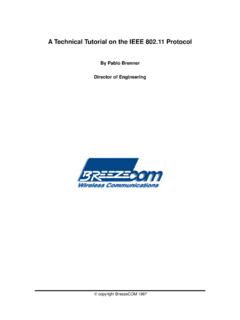
3 NEL's triangle wave, as shown in figure 2. HS-7800 Oscillator has less than 40. Figure 2 picoseconds of cycle-to-cycle jitter. EMI Suppression This method of EMI suppression These are results from tests by outside was patented in 1942 by Hedy Lamar sources. and George Antheil. The patent was Phase locked loop devices are for using a frequency hopping method commonly very noisy and exhibit very to shield radio-controlled torpedoes in poor jitter performance. World War II. Frequency modulation has a much lower harmonic amplitude than that of an unmodulated signal, as 2 Oscillator Reduces EMI from Computers July 4th, 1997. Figure 3 Oscillator Block Diagram NEL uses a series of noise suppression The frequency divider and the The output symmetry will hold plus or devices within this device to provide feedback divider sections are minus percent versus all conditions. good noise immunity. The noise programmed to divide each output until The measure of jitter is less than forty suppression and the noise isolation of the frequencies are equal.
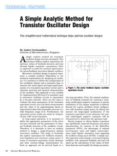
4 This is at picoseconds when measured cycle to the different stages contribute to the about four MHz. These are CMOS cycle. low jitter readings. devices of micron line widths The unit is fabricated on ceramic technology. substrate material and with conductive The frequency detector system epoxies. The construction is all chip Operation detects the offset between the voltage- and wire. NEL does not use plastic A block diagram of the internal controlled Oscillator and the Crystal packaged part within the Oscillator . operation of this product is shown in Oscillator . The detector activates the This allows for better aging and there is figure 3. There are three main parts; charge pump to compensate the no chance of the plastic package the Oscillator section, the phase locked voltage-controlled Oscillator to track exploding during solder reflow. The loop section and the ECL output with the Crystal Oscillator .
5 Oscillator is able to withstand up to 253. section. The modulating waveform was EC of reflow heat. This chip and wire The Oscillator section was custom discussed above in the EMI suppression construction also allows NEL to use a designed by NEL to provide a high section. The waveform is 20 kHz to 100 mounted Crystal blank instead of a stability oscillation over varying kHz pseudo triangle wave. The Crystal sealed in a holder. The use of a conditions. This Oscillator meets a plus frequency of modulation is divided from Crystal blank only allows NEL to offer or minus twenty-three parts per million the input to the phase detector from the a reduced height, as short as ". tolerance from 0EC to 70EC. This input divider. This modulation rides on without glass stand-offs. includes a plus or minus ten parts per top of the offset charge pump and is sent million tolerance for temperature into the voltage controlled Oscillator .
6 Deviations, plus or minus ten parts per The voltage-controlled Oscillator million for tolerance of setting the will operate at frequencies more than center frequency, and plus or minus 135 MHz and holds a 45 to 55 percent three parts per million for voltage and symmetry on its CMOS-output load variations. This section provides waveform. Post dividers make this a low power Crystal oscillation that product operable from 10 MHz to 135. tracks the Crystal angle. This unit is MHz. specially processed to be final plated to This waveform is then shaped from the exact average frequency over time CMOS to ECL using an ECL gate. The The gold-plated base and lead are while it is being modulated. This output of the wave shaping gate is fed great for solder or conductive epoxy accounts for any nonlinearities in the into a buffer stage for isolation and mounting. The unit is backfilled with deviation causing an average frequency waveform integrity.
7 92 percent helium, sealed and vacuum error. The ECL output buffer is a checked for minute leaks of three time complementary output 10K ECL gate. ten to the minus eighth torr. This type 3 Oscillator Reduces EMI from Computers July 4th, 1997. of sealing assures good aging and this unit in a wide range of deviations thermal conduction. and output frequencies. The output waveform characteristics, demodulate References: characteristics, and the DC Lexmark International, Inc. characteristics are tested on each unit Patent 5,631,920. for compliance to specification. Dow Jones News Service DC Supply Acticle Hedy Stuff . The unit is tested at NEL using a Written by: split supply of Vcc equal to plus two Reliability volts dc and Vee equal to minus three All of NEL's products go through Chet B. Chesher Design Engineer volts dc and terminating the output strict reliability testing before they are NEL Frequency Controls, Inc.
8 With a dc 50 load. NEL also tests the released for sale. These units have been 357 Beloit Street product using a 82 resistor from Vcc placed in an oven at one 125 EC for two- Burlington, WI. to the output and 130 resistor from thousand hours and not one has failed to 53105. the output to Vee. operate. Voice (414)763-3591. NEL constructs this unit in a class Fax (414)763-2881. SS(+ ) Vcc(+ ) Vcc(+ ). 500 clean room. The clean environment C1 C2 C3 C4 C5 C6 C7 C8 C9 C10 C11 C12 C13 C14. keeps the oscillators aging low with a Sw1. 100PF 560PF 1000PF 2200PF .01UF .47UF 100PF 560PF 1000PF 2200PF .01UF .47UF. Scope Keep short very high reliability. Strict anti-static as possible Outputs 1 Reset 10EL16 Vcc 8 SMA procedures are in place to prevent 2 7 SMA. HS-7809. R1. 51. 3 6 damage that may shorten the life of the 4 Vbb Vee 5. C29. 100PF. C30. 560PF. C31. 1000PF. C32. 2200PF. C33..01UF. C34..47UF. C35. product.
9 All units are tested 100 percent at C15 C16 C17 C18 C19 C20 C21. 100PF 560PF 1000PF 2200PF .01UF .47UF. C36 C37 C38 C39 C40 C41 C42. 100PF 560PF 1000PF 2200PF .01UF .47UF. room temperature and AQL testing is Vee C22 C23 C24 C25 C26 C27 C28. Vee( ). 100PF 560PF 1000PF 2200PF .01UF .47UF. The information contained in this document, is to be considered proprietary and may not be reproduced, transmitted or copied provided over temperature on each lot without the express permission of NEL Frequency Controls, Inc. Vee NEL FREQUENCY CONTROLS, INC. 357 Beloit Street Burlington, Wisconsin 53105. Vee( ) DWN. CBC. - CHK. - TITLE. Schematic - CHK APP. X227 Production - Fixture produced. NEL does not use - - SCALE SIZE DWG NO. REV. NONE. 10 : 1. DATE. 05/29/97. - A. A X227 -fixture - PAGE 11OF 22 FILENAME fixtr1. - .DWG. chlorofluorocarbons or other This Oscillator comes in two case environmentally harmful chemicals.
10 Styles. The first style has the case tied Scrap materials are recycled whenever it to Vee (pin seven) and a single output is possible. on pin eight. This unit is NEL is ISO 9001 certified, showing recommended to be operated on plus their commitment to total quality and five volts dc because of case to ground customer satisfaction. shorting. The second style has complementary outputs and the case is Conclusion tied to Vcc (pin fourteen). This case is The performance of Computers designed with a minus five volts dc today are forcing the clock frequencies supply, because it will keep the case at higher, and increasing the number of ground potential. Keeping the case at gates. This equates to electro-magnetic ground potential is important to keep interference. The HS-7800 Oscillator the noise from radiating onto the allow for reduction of these emissions circuit. without costly enclosure designs or multilayer ground plane PC-board The unit draws approximately 60 construction.