Transcription of CSEE!4840!Embedded!systemdesign! - Columbia University
1 flappy Bird CSEE 4840 Embedded system design Wei Zheng wz2299 Gaoyuan Zhang gz2216 Junhui Zhang jz2605 Yen Hsi Lin yl3284 Contents 1. Overview .. 2 2. High Level Design .. 3 3. Game Logic Controller .. 4 4. Game stuff preparation .. 6 5. VGA Device Drive .. 7 6. Sprite Controllers and VGA Display .. 7 7. Audio .. 9 8. Lessons learned and issue .. 11 9. Advice and future work .. 11 10. Contribution .. 11 11. Milestone .. 12 HDL Code .. 13 13. C Code .. 70 1 1. Overview In this project, we design and implement a flappy Bird like video game on the SoCKit development board. flappy Bird is a very popular mobile game on Android platform, driving a lot of people crazy. In this game, the player can control the vertical movement of bird ( every pressing on the keyboard makes the bird leap upward for a little bit, and the bird will fall freely without control ).
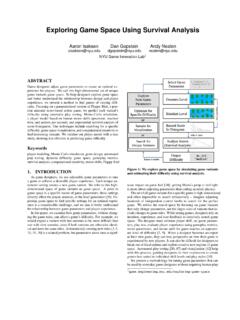
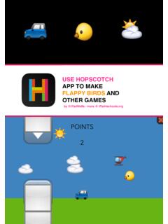
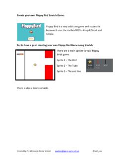
2 As soon as the game begins, tubes will keep appearing from the right side of the screen and moving leftwards. (so that it seems like the bird flying forward). The goal of this game is to control the bird, dodging and passing the incoming tubes, as many as possible. The game is endless until the bird eventually hit one of the tubes, ground, or ceiling. Figure 1 is the start screen of flappy Bird. The title " flappy Bird" is shown in the middle of the uppers side of the screen. The bird is also displayed on the background. Figure 1. Start screen for flappy Bird Figure 2 shows the screen when the game is on. The three pillars are displayed on the screen, and so is the score, on top of the background or the pillar. (instead of the title) Figure 2.
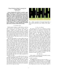
3 Game- on screen for flappy Bird 2 2. High Level Design Primary components that constitutes our game includes the ARM core (game logic), device driver, USB controller to control the input from keyboard, Sprite controller (control the display of sprites), audio controller, SDRAM ( store all the data needed in game logic). The game logic module interfaces with several other modules including the USB keyboard, by receiving the control signal; as well as the device driver in order to control the audio and display of sprites, including the positions of pillars and birds, the length of the pillars and the score. Sprite controller is connected to VGA Controller, which is responsible for the display of all the images, and audio controller is connected to audio CODEC on the SoCKit board.
4 Each of the components in our design will be discussed in detail below. Figure 3. High level block diagram 3 3. Game Logic Controller We implement the game logic by using C programming language. The game logic controller should realize the functions which are indicated below: updating the location of the bird from the keyboard, implementing the game rule (whether the game is over or not, computing how many pillars the bird has passed), generating the appropriate audio in terms of the game rule, and controlling the generation of sprites. Based on the functions given above, there should be 3 submodules for the game logic controller, the figure of which is shown below: Figure 4. Game logic block diagram 1. Game rules: This is the core submodule of the game logic controller which interfaces with all of the other submodules, instructing them what to do based on the game rules.
5 The rules are implemented by the updated position of bird from the keyboard, and the current position of the pillars. Appropriate audio is chosen corresponding to the rules (whether the game is over or not). 2. Sprite generator: 1. Pillars: This submodule keeps updating the X coordinates of the pillars that has already appeared on the screen (by decrementing them in every cycle), as well as the length of the upcoming pillar that is going to appear from the right side of the screen (which is actually the number of "partial" pillars that stack). The length of the pillar should be random, as long as the distance between the pillars is constant. Once the sprite moves out of the screen (in this case, x coordinate of any one of the pillars becomes zero), we reset the coordinate so that it can reappear from the right side of the screen.
6 2. Bird: Bird acts like in real world that its jump and fall will be affect by the gravity. When 4 we implement the object motion formula in our code, time calculation is an issue that we use a counter counting instead of using system clock. We put the delay in our loop and try a suitable count number being our time unit. In addition, we add a status variable to indicate if the bird status is rising or falling. It cooperates with our jumping and falling function with iteration loop supporting continuous jumping without multi- thread. 3. Score: Every time the bird passes one of the pillars, the "Game Rules" submodule sends a signal, which will make the score increment by 1. Since the sprite for displaying the score are separated into 3 parts, hundreds, tens and digits, we need to extract them from the score before sending them to the hardware.
7 4. Title: The display of the title " flappy Bird" depends on whether the game starts. When the game is over, press "enter" to restart, and the title would be displayed instantly. Since each signal sent from software to hardware has 8 bits, we only use one of them as the control signal to display the title, so that we can use other bits for other purposes, which improve efficiency. 3. Audio generator: There are three audios to be played, one played once pressing the "jump" button, and two played consecutively once the game is over. The selection of the audio is based on the signals from "Game Rule" submodule. 5 4. Game stuff preparation The preparations required for the graphics and audio are similar. First the image and audio files had to be searched for online.
8 Once we agreed on the images and audio for the game, we edited them to fit our game design. Finally, both the image and audio files had to be converted to MIF format in order to be stored in the on- chip ROM blocks. Image preparation For image preparation, first we resize the image to the size we will use. Then we do image segmentation of the images to separate the useful part. Then we set the background to a pure color so that the sprite controller can easily recognize the background part and remove it. Finally we convert the processed image to MIF files. In FPGA we will use different module to read the data of the MIF files. The image we processed is showed below. Blocks background bird number Pipe sun Numbers 1 1 10 2 1 Pixels 128*64 40*40 51*33 20*125 50*50 ROM 24567 4800 1683 2500 7500 size(bytes) example Audio preparation For audio preparation, it is familiar as the image processing.
9 In this game, we totally used three sound segment: Super Mario jumping sound, Super Mario death sound and Doodle Jump falling down sound. For Super Mario death sound, it is a segment with 22050 Hz sampling rate and 65536 samples. The codec sampling rate of FPGA we use is 44100 Hz. So we first upsample the sound segment by a factor of 2. Then it becomes a segment of 131072 samples. The maximum of MegaWizard ROM words is 65536. Thus we should divide the segment into two parts each of them consists 65535 samples. Then convert them into MIF files. The process of jumping sound and falling down sound is same as the death sound. 6 5. VGA Device Drive The VGA module is actually a memory- mapped slave, which connects to the Avalon bus through the lightweight AXI bridge.
10 The HPS uses 4- bit address bits to access 16 location that store 8 bits data. More specifically, The software use ioctl to call the iowrite function in the device driver and specify the registers' address(a base address of the vga slave plus the offset address which is specified in the device tree ) to write. We use Qsys to connect everything between vga_led and the HPS up. 6. Sprite Controllers and VGA Display VGA display is the core part of our project, VGA scan the screen and display pixels of graph. The video display controller has two major blocks, the VGA controller and the Sprite Controller. (see figure 4). Detailed introductions of Sprite Controller and VGA Controller are as following: Figure5. VGA display block diagram 1. VGA Controller: This module generates the VGA signals needed by the VGA interface and also hcount and vcount values that are used in Sprite controller.