Transcription of CUMMINS PT FUEL SYSTEM - liberatedmanuals.com
1 DEPARTMENT OF THE ARMY TECHNICAL MANUALTM 55-4018-1 DEPARTMENT OF THE AIR FORCE TECHNICAL ORDERTO 38G1-6-21 CUMMINSPT fuel SYSTEMDEPARTMENTS OF THE ARMY AND THE AIR FORCESEPTEMBER 1956 This technical manual contains copyrighted materialDEPARTMENTS OF THE ARMY ANDTHE AIR FORCEWASHINGTON 26, DC., 5 September 1966TM 55-4018-1/TO 88G1-6-21 is published for the use of all concerned.[AG 406 (27 Jul 56)]BY ORDER OF THE SECRETARICE OF THE ARMY AND THE AIR FORCE:MAXWELL D. TAYLOR,General, United States Army,Chief of StaffOFFICIAL:JOHN A. KLEIN,Major General, United States Army,The Adjutant F. TWINING,Chief of Staff, United States Air :E. E. TORO,Colonel, United States Air Force,Air Adjutant :Active Army:Tec Svc, DA (2)Army Maint Bd (2)Trans Bd (1)Mq CONARC (2)Army AA Comd (2)OS Maj Comd (2)OS Base Comd (1)Log Comd (2)MDW (1)Armies (2)Trans Sup & Maint Comd (15)Trans Sch (Trans Sec, Gen Depots (5)Trans Depots (5)POE (OS) (1)Trans Terminal Comd (1)Army Terminal (1)OS Sup Agencies (1)NG: : explanation of abbreviations used, GOVERNMENT PRINTING OFFICE:TABLE OF CONTENTSSECTION IOperating.)
2 fuel ,.. IIFuel SYSTEM ..Changing Supply Tanks ..2-4 SECTION IIIS ervice and .. fuel Pump Filter Element a PT Pump on the Injectors on the IVFuel Pump Assembly and .. VMaintenance and Testing of ..SECTION VITrouble-Shooting the fuel ..31-1 to 1-62-1 to 2-83-1 to 3-54-1 to 4-265-1 to 5-26-1 to 6-24 INDEXA djusting engine idle fuel pump on standard torque converter variable-speed leak of fuel of fuel of fuel pump on , 4-24 Capscrews and fuel fuel fuel pump injectors ..5-1 Clean injectors on engine ..3-4 Diagram, fuel , fuel pump ..4-1 Disassembly, , 2-2 Drive shaft bushing ..4-6 Front cover , 4-9 fuel , 3-1, 4-4, 4-15 fuel inlet connections ..1-6, 2-1 fuel , 1-6, 2-2, , 2-2 fuel pressure , 4-21 fuel , 2-1, 4-1, 4-20 fuel pump pump disassembly ..4-1 fuel supply , 4-21 fuel SYSTEM , 4-2, 4-7 General , idle and maximum , 3-2, 4-16 Governor plunger.
3 4-2, 4-8, 4-18 Governor spring guide ..4-16 Governor spring pack , 4-16 Governor, torque , 3-3 Governor, , 3-3, 4-17 Governed , 4-22, 4-23, 4-24 Idle governor ..1-3, 3-2, 4-16 Injectors ..1-5, 2-1, 3-2, 5-1 Injector cleaning, cleaning, on orifice ..4-20 Manifold , 4-22, 4-24 Material for calibrating pumps ..4-21 Maximum speed , 3-2, 4-16 Needle , , , cleaning ..5-1 Parts replacement ..4-6 Piping, fuel ..2-4 Pressing lubricant ..4-6 Pressure regulator ..1-3, 4-1, 4-19, 4-22 Pressure regulator spring load ..4-22 Pressure regulator setting ..4-20, 4-22, 4-24 Priming the , check on , 4-3, 4-7 Pump testing ..4-20 Screen, fuel ..3-1, 4-4, 4-15 Section I Operation Principles ..1-1 Section II fuel SYSTEM Installation ..2-1 Section III fuel SYSTEM Service andAdjustments ..3-1 Section IV fuel Pump Assembly V Maintenance of VI Trouble Shooting theFuel and , 2-3, 4-19 Spring pack housing ..4-4, 4-16 Supply , 2-3 Table, injector , idle speed.
4 4-20, 4-24 Table, manifold , 4-24 Tachometer , 4-8, 4-15 Test equipment ..3-4, 4-21, , 4-2, 4-18 Throttle , 4-23, 4-24 Tools ..4-5 Torque converter governor ..1-4, 3-3 Trouble shooting ..6-1 Trouble shooting rebuilding ..4-5 Variable-speed , 3-3 Vise and holding fuel pump with maximum speed governorPT fuel pump with variable speed governorPT fuel pump with torque converter governorOperation and MaintenanceCUMMINS PT fuel SYSTEMSECTION IOperating PrinciplesCummins PT fuel SYSTEM is a completely newapplication of basic hydraulic principles to the dieselengine fuel SYSTEM . It is a CUMMINS design for CumminsDiesels. The identifying letters, "PT," are an abbreviationfor "pressure-time."The principle of the PT fuel SYSTEM is based on thefact that by changing the pressure of a liquid flowingthrough a pipe you change the amount of liquid comingout of the open end: Increasing the pressure increasesthe flow or the amount of liquid delivered, and vice applying this simple principle to the diesel fuel SYSTEM itwas necessary to provide:1.
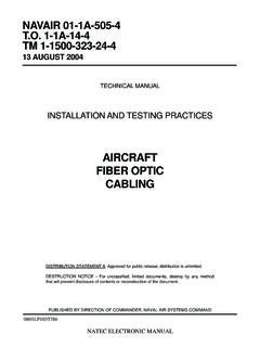
5 A fuel pump to draw fuel from the fuel tankFigure 1-1. PT fuel SYSTEM - fuel flow diagram1-1and deliver it to individual injectors for means of controlling the pressure of the fuelbeing delivered by the fuel pump to the injectorsso the individual cylinders would receive the rightamount of fuel for the power required of passages of the proper size and type so thatthe fuel will be distributed to all injectors andcylinders with equal pressure under all speed andload to receive low-pressure fuel from thefuel pump and deliver it into the individualcombustion chambers at the right time, in equalquantity and proper condition to PT fuel SYSTEM consists of the fuel pump (withgovernor), the supply and drain lines, and the of these is described in detail in the PumpThe fuel timing is made up of three main gear pump which draws fuel from the supplytank and delivers it under pressure through thepump and supply lines to the individual pressure regulator which limits the pressureof the fuel to the governor and throttle which act independentlyof the pressure regulator to control fuel pressureto the fuel pump is coupled to the compressor or fuelpump drive which is driven from the engine gear fuel pump main shaft turns at engine crankshaftspeed, and drives the gear pump, governor andtachometer location of these units in the fuel pump housing isindicated in Fig.
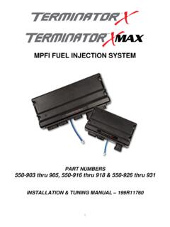
6 PUMP: The gear pump is located at the rear ofthe fuel pump and it is driven by theFigure 1-2. Cross section PT pump with idling and high speed mechanical governor1-2 Figure 1-3. fuel flow through the fuel pumpmain shaft. This unit consists of a single set of gears topick-up and deliver fuel throughout the fuel SYSTEM . Fromthe gear pump fuel flows through the filter screen and tothe pressure REGULATOR: 'The pressure regulator is aby-pass valve to regulate the fuel , under pressure,supplied to the injectors. By-passed fuel flows back to thesuction side of the gear : fuel for the engine flows past the pressureregulator to the throttle shaft. Idle fuel passes around theshaft to the idle jet in the governor. For operation aboveidle, fuel passes through the throttling hole in the shaftand enters the governor through the primary AND HIGH-SPEED MECHANICAL GOVERNOR:Mechanical governor action is provided by a SYSTEM ofsprings and weights, and it has two functions.
7 First; thegovernor maintains sufficient fuel for idling with thethrottle control in idle position and second; it cuts off fuelabove maximum rated rpm. The idle springs in thegovernor spring pack position the governor plunger so theidle fuel jet is opened enough to permit passage of fuel tomaintain engine idle operation between idle and maximum speeds, fuel flows through the governor to the injectors in accordwith the engine requirements as controlled by the throttleand limited by the pressure regulator. When the enginereaches governed speed, the governor weights move thegovernor plunger and fuel passages to the fuel supplymanifold are shut off. At the same time another passageopens and dumps the fuel to the supply manifold backinto the main pump body. In this manner engine speed iscontrolled and limited by the governor regardless ofthrottle position. fuel leaving the governor travelsthrough the shut-down valve, inlet supply lines and on intothe 1-4.
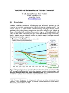
8 Flange mounted fuel pump with variablespeed governorVARIABLE-SPEED MECHANICAL GOVERNOR: Thisgovernor is designed to meet the requirements ofmachinery on which tile engine must operate at aconstant speed but where extremely close regulation isnot for different rpm can be made by meansof a lever control or adjusting screw. At full-rated speed,this governor this a speed droop between full-load anti no-load of approximately eight percent. A cross-section ofthis governor is shown in Fig. a variable-speed governor, this unit is suited to thevarying speed requirements of cranes, shovels, etc., inwhich the same engine is used for propelling the unit anddriving a pump or other fixed-speed a constant-speed governor, this unit providescontrol for pumps, nonparalleled generators and otherapplications where close regulation (variation between no-load and full-load speeds) is not CONVERTER GOVERNOR: When a torqueconverter is used to connect the engine with its drivenunit, an auxiliary governor may be driven off the torqueconverter output shaft toFigure 1-5.
9 Cross Action and fuel flow through torque converter governor and fuel pump1-4exercise control over the engine governor and to limitconverter output shaft speed. The engine governor andthe converter governor must be adjusted to work PT torque converter governor is fundamentallytwo mechanical variable-speed governors in series - -onedriven by the engine and the other by the converter. SeeFigs. 1-4 & engine governor, in addition to giving a variableengine speed acts as an overspeed and idle-speedgovernor while the converter-driven governor iscontrolling the engine. Each governor has its own controllever and speed adjusting converter driven governor works on the sameprinciples as the standard engine governor except itcannot cut off fuel to the idle jet in the engine drivengovernor. This insures that if the converter tailshaftoverspeeds it will not stop the engine.
10 See Fig. 1-5 shows the position of the governor plungersunder different engine and converter speed circulates through the injector at all times exceptduring a short period following injection into the the inlet connection fuel flows down the inletpassage of the injector, around the injector plunger,Figure 1-6. Injector cross sectionbetween the body end and cup, up the drain passage tothe drain connections and manifold and back to thesupply the plunger comes up the injector feed passage isopened and fuel flows through the metering orifice intothe cup, at the same time fuel flows past the cup and outthe drain orifice. The amount of fuel which enters the cupis controlled by the fuel pressure against the meteringorifice. fuel pressure is controlled by the fuel pump aspreviously plunger during injection comes down until themetering orifice is closed and the fuel in the cup isinjected into the cylinder.