Transcription of Current Transformers - Te Connectivity
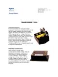
1 Tyco Electronics Corporation Crompton Instruments 1610 Cobb International Parkway, Unit #4 Kennesaw, GA 30152 Tel. 770-425-8903 Fax. 770-423-7194 Current Transformers Current Transformers (CT's) provide a simple, inexpensive and yet accurate means of sensing Current flow in power conductors. They are available in 3 basic configurations: 1. Ring Core CT's are available for measuring currents from 50 to 5000 amps, with windows (power conductor opening size) from 1" to 8" diameter. 2. Split Core CT's are available for measuring currents from 100 to 5000 amps, with windows in varying sizes from 1" by 2" to 13" by 30". Split core CT's have one end removable so that the load conductor or bus bar does not have to be disconnected to install the CT. 3. Wound Primary CT's are designed to measure currents from 1 amp to 100 amps.
2 Since the load Current passes through primary windings in the CT, screw terminals are provided for the load and secondary conductors. Wound primary CT's are available in ratios from :5 to 100:5 (Models 189 and 190 are examples of wound primary CT's). CT's used with watt transducers enable the owner to control demand as well as monitor building and/or tenant power consumption. When CT's are used with Current Transducers, the result is an excellent method of diagnosing the performance of fans, pumps, chillers, etc. The Model 4 CMA and 4 CTV Current Transducers provide alarms for each motor so the owner is warned immediately of any abnormal operating condition. Low pump flows will be alarmed if the strainer is dirty or the coupling is broken. Low fan flows will be alarmed if filters are dirty, belts are slipping, or dampers (fire, smoke, etc.)
3 Are closed. High motor loads will alarm if bearings are dry or worn, or belts are out of alignment. CT's are designed to handle motor inrush currents, so no extra precaution is needed to monitor motors. Monitoring Multiple Loads With One Watt Transducer There are two methods of monitoring multiple loads with one watt transducer. All loads must be fed from the same service and the voltage must be sensed from one source. 1. The first method can be used to monitor up to 5 feeders with wide ranging loads. The secondaries of the feeder CT's are connected to a Model 190 Summing Transformer. The output of the summing transformer is connected to the input of a WT Series Watt Transducer. Typically the CT ratios must be the same, but different ratios can be used with a specially built summing transformer. Each summing transformer must be connected to one phase only.
4 It takes three summing Transformers and fifteen feeder CT's to monitor and totalize five three-phase loads. When using summing Transformers , add the primary CT currents to calculate the kW and kWh outputs. For example, when summing five 1000:5 CT's use a CT ratio of 5000:5 to determine the outputs. When using low amperage (200A) CT's with a summing transformer, be sure to check the burden on the CT's as the summing transformer adds burden. 2. The second method is to parallel CT inputs at the transducer. This method would require: 1. balanced loads, 2. same ratio CT's, 3. paralleling at transducer only, 4. grounding at transducer only, 5. burden capability to be reduced by the number of CT's ( , 3 CT's give 1/3 capability), 6. CT's to be oversized so the total secondary Current does not exceed the 5 amp rating, which reduces accuracy.
5 Since this method requires ideal conditions, it is generally better to use a summing transformer. CT Accuracy A CT is most accurate at rated Current with a low burden (load). Accuracy decreases with increased burden (load) or low line Current . In sizing CT's the conductor size and distance is important. Improper sizing of Current Transformers or long secondary conductor runs with undersized cable can result in poor accuracy. Burden (load) Information On CT's The external load ( , meters, transducers, etc.) applied to the secondary of a CT is called the burden. The burden can be expressed in volt-amperes: VA = I2 x Z Z = Total CT secondary impedance I = Secondary Current (Generally 1 or 5 amps) Total burden is the sum of: 1. Device (transducer, meter, etc.) Burden - Furnished by the manufacturer. 2. Burden of Interconnecting Leads - can be calculated by using the above formula.
6 Use conductor resistance (total to the device and back) for Z (See Power Equations for chart of impedance of wire sizes). 3. Internal Burden of CT Windings - This is so small that it can generally be ignored. Exact burden calculations are usually not necessary unless the CT ratio is below 200:5. If necessary, see the section on burden calculations The VA burden that a CT will handle varies with the ratio and physical size of the CT. The burden capacity for each Model CT is specified on the data sheet. A small 50:5 Model 2RL will only handle 1 VA of burden capacity. A large 2000:5 Model 170RL will handle a burden capacity of 100 VA. As a rule of thumb, use a 1 amp input (WT-1) watt transducer for a 200 amp or less feeder. The 5 amp (WT-5) transducer can be used for feeders less than 100 amps when connected to wound primary CT's (Model 189).
7 Sizing CT's On new construction, size the CT to handle about 80% of the circuit breaker capacity. If the building is served by a 2000 amp breaker, use 1600 amp (2000 x ) CT's. For older buildings, the peak demand can generally be determined from the power company or from past billings. In this case add 20 to 30% to the peak demand and size the CT's for this load. If the peak demand was 500 kW, the peak Current on a 480/3/60 system would be: 500,000 / (480 x x pf) = 669 amps This assumes a power factor. (Peak Current would be higher with a lower power factor.) Use CT's about 20% larger. 800:5 CT's would be a good selection. For older buildings with no demand history, size the CT's the same as for new construction. Where possible, use multi-tap CT's so that the ratio can be reduced if the maximum load is much less than 80% of the breaker size.
8 CT's that are used to monitor motor loads can be sized from the nameplate full load motor amps. Selecting CT's A "Selection Guide" is provided in this catalog to aid in selecting the type of CT for your application. Non-standard ratios can be obtained by looping the conductor through the window to add or subtract Current flow. (See Example in Figure 2.) The relationship of the ratio of primary and secondary turns is expressed in the following formula: Ka = (Kn Nsa) / Np Ka = Actual transformation ratio Kn = Nameplate transformation ratio Transformation ratio = primary Current / secondary Current Nsa = Number of secondary turns added or subtracted (To Add - loop X1 lead through H1. To Subtract - loop X1 opposite H1) Np = Number of primary turns 3 Primary Loops + 2 Secondary Loops added Example: An application requires a 20:5 CT ratio, but only a 50:5 CT is available.
9 Using the above formula it can be determined that by using 3 primary loops and adding 2 secondary loops that a 20:5 actual ratio will be obtained. Ka = (Kn Nsa) / Np = (10 + 2) / 3 = 4 Actual CT Ratio = 20:5 Mounting CT's CT's are generally located in the main breaker panel or in branch distribution panels where space is always at a premium. Since CT's do not have to be installed 90 degrees to the conductor run (the conductors can go through the CT at any angle) they are generally held in place with plastic tie wraps. CT's with mounting feet are available if appearance is important and there is enough room to accommodate this type of mounting arrangement. Installing CT's Window type CT's should be mounted with the H1 side of the window towards the power source.
10 The X1 secondary terminal is the polarity terminal (Figure 3).The polarity marks of a Current transformer indicate that when a primary Current enters at the polarity mark (H1) of the primary, a Current in phase with the primary Current and proportional to it in magnitude will leave the polarity terminal of the secondary (X1). If a CT test switch is used, the switch must have a "make-before-break" contact pattern to assure that the CT is not open-circuited during transition. Normally CT's should not be installed on "Hot" services. The power should be disconnected when the CT's are installed. Many times this is not possible because of critical loads such as computers, laboratories, etc. that cannot be shut down. Split core CT's should not be installed on "Hot" uninsulated bus bars under any conditions. On existing cable installations where the monitoring point is not close to a cable end, small ring core CT's can be shunt installed on #8 cable or smaller by using Hot Tap insulation piercing connectors similar to those made by 3M.