Transcription of Installation instructions Analogue DIN Panel Meters
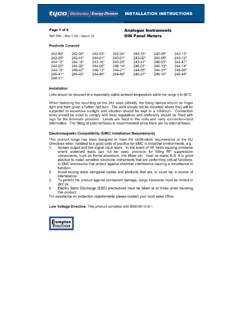
1 Installation instructionsAnalogue DIN Panel Meters Products Covered (part number is prefixed with E for Eurodin) Caution: Risk of Danger These instructions contain important safety information: Read before starting Installation or servicing of the equipment Caution: Risk of Electric Shock 242-02* 243-01* 244-01* 246-01* 244-16* 246-41* 242-03* 243-02* 244-02* 246-03* 244-21* 246-42* 242-04* 243-05* 244-03* 246-05* 244-25* 246-45* 242-05* 243-12* 244-05* 246-10* 244-31* 242-15* 243-15* 244-12* 246-13* 244-41* 242-25* 243-16* 244-13* 246-14* 244-42* 242-41* 243-25* 244-14* 246-21* 244-45* 242-89* 243-41* 244-15* 246-31* 244-80* This product range includes a wide range of functions, including AC Ammeters and maximum demand Meters ; AC Voltmeters; DC Ammeters and milliammeters; DC Voltmeters and millivoltmeters; Elapsed time Meters ; Frequency Meters ; AC wattmeters and var Meters ; Power factor Meters ; phase sequence Meters ; Rotary synchroscope, temperature and tap position indicators Marking and ratings Body side labels show function, electrical rating, and connection diagram, where there are more than two terminals on the unit.
2 For two terminal units, the terminals are connected directly across the input to be measured. Terminal numbers are moulded into the base adjacent to each terminal stud and corresponding numbers appear on the connection diagram. Note that the electrical rating may differ from the dial scale marking, and the unit side label is definitive. These Meters are intended for a rated temperature range, is -20/+60 deg C and up to 80% relative humidity, and only for indoor use at an altitude of less than 2000m. Shock maximum level is 30g. Installation The meter should be installed in line with the requirements of the local electrical code. It should be installed in a dry position, not in direct sunlight and where the ambient temperature is reasonably stable and within ratings above. These units are only for built in use and with terminals inaccessible to users after Installation and should be mounted to a DIN Panel cut-out up to a maximum thickness of 5 mm.
3 Mounting is by 2 opposed corner clamps. It may be convenient to use a 7mm screwdriver style nut driver to engage the barrel nuts on those models with plastic nuts, particularly when starting the thread, but great care must be taken not to over tighten. It is very easy to cause damage with excessive torque when using a nut driver, so final tightening should be performed with finger pressure only. For Eurodin products, a 3mm flat blade screwdriver can be used to rotate the Panel clamp shaft. Fusing and connections External voltage transformers and current transformers may be used where appropriate to extend the range, provided that the ratings marked on the side label are not exceeded at point of connection to meter. These products are designed for permanently connected use, normal condition measurement category III, pollution degree 2 ( non ventilated panels or ventilated panels with filters, without condensation occurring), basic insulation, for rated voltage.
4 Connection diagrams shown on the unit side label should be carefully followed to ensure correct polarity and phase rotation where applicable. Terminals are intended for use with insulated ring lugs. Ensure a minimum spacing of ( ) between uninsulated parts of adjacent ring lugs. Tighten terminal screws to 2Nm ( ft/Lb) only. These products do not have internal fuses therefore external fuses must be used for safety protection under fault conditions. Voltage input lines where required must be fused with a quick blow fuse 1A maximum. Auxiliary supply lines, where required must be fused with a slow blow fuse rated 1A maximum. Current metering circuits directly connected in line with the load must be fused at the rated current for the meter. Where fitted, current transformer (CT) secondaries must be connected to protective earth in accordance with local regulations. Do not fuse CT circuits.
5 The equipment into which this meter is installed must have a clearly marked adjacent means of isolating the supply voltage to permit safe access for subsequent maintenance. Ensure supply circuits are rated for meter VA: > Choice of associated components Choose fuses of a voltage rating equal to or exceeding the rated voltage of the circuit into which the meter is connected and of a type and with a breaking capacity appropriate to the supply to which the fuse is connected. INST 24x Iss June 08 1 of 2 Tyco Electronics UK Limited - Energy Division Freebournes Road, Witham, Essex, CM8 3AH, UK Phone: +44 (0)870 870 7500 Fax: +44 (0)870 240 5287 All of the above information, including drawings, illustrations and graphic designs, reflects our present understanding and is to the best of our knowledge and belief correct and reliable. Users, however, should independently evaluate the suitability of each product for the desired application.
6 Under no circumstances does this constitute an assurance of any particular quality or performance. Such an assurance is only provided in the context of our product specifications or explicit contractual arrangements. Our liability for these products is set forth in our standard terms and conditions of logo and Tyco Electronics are trademarks. CROMPTON is a trademark of Crompton Parkinson Ltd. and is used by Tyco Electronics under licence. INST 24x Iss June 08 2 of 2 Connection wires and ring lugs should be rated for at least 1A for voltage and auxiliary lines and to at least the rated current for current measuring circuits. Additionally, wires for DC current Meters rated over 50mA must be rated at 75 deg C or greater. Ensure cables and ring lugs have a voltage insulation rating equal to or greater than the rated voltage of the circuit to which they are connected. CT cable impedance should ensure that CT VA rating is not exceeded and it s accuracy impaired.
7 Cleaning and maintenance As required, wipe the front face with a damp cloth, ensuring that no moisture enters the unit or penetrates behind the mounting Panel . No maintenance is required beyond periodically checking the mechanical zero of the meter as described overleaf in commissioning , if necessary removing any accumulations of dust or other foreign matter from the terminal area and ensuring that connections remain tight. Warning During normal operation, voltages hazardous to life may be present at some of the terminals of this unit. Installation and maintenance should be performed only by qualified, properly trained personnel' abiding by local regulations. Ensure all supplies are de-energised before attempting connection or other procedures. Never open circuit the secondary winding of an energised current transformer. If this equipment is used in a manner not specified by the manufacturer, protection provided by the equipment may be impaired.
8 Electromagnetic Compatibility This unit has been designed to provide protection against EM ( electro -magnetic) interference in line with requirements of CE and other regulations. Precautions necessary to provide proper operation of this and adjacent equipment will be Installation dependent and so the following can only be general guidance:- Avoid routing wiring to these products alongside cables and products that are, or could be, a source of interference. Where required, the auxiliary supply to the unit should not be subject to excessive interference. In some cases, a supply line filter may be required. To protect the product against incorrect operation or permanent damage, surges and transients must be controlled. It is good EMC practice to suppress transients and surges at the source. Connecting leads may require the fitting of RF suppression components, such as ferrite absorbers or line filters It is good practice to install sensitive electronic instruments that are performing critical functions in EMC enclosures that protect against electrical interference causing a disturbance in function.
9 For assistance on protection requirements please contact your local sales office. Commissioning The units are calibrated at the factory for full accuracy. No further adjustments are required except to check the zero position. With the meter in the intended attitude, adjust the centre slotted adjuster for scale zero without electrical input signal. It is recommended that after Installation , test signals are applied to confirm correct indication and that, where applicable, CT phasing is correct and voltage and current connections match. Bezel Panel cut-out (242) 48x48 45x45 (243) 72x72 68x68 (244) 96x96 92x92 (246) 144x144 138x138 Terminal Covers Terminal boots are available for all products. Terminal covers are available for 242, 243 and 244 products. On the 242 the cover is held in place with two screws. On 243 and 244 90 scale the cover is fixed by one screw. All remaining types of 243 and 244 have a push fit cover.
10 This cover is fitted after the meter has been installed in the Panel and all wire connections made.