Transcription of D5 Continuous Optical Sorting of HeLa Cells and ...
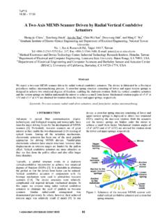
1 D5. 11 :45 - 12:00. Continuous Optical Sorting of HeLa Cells and microparticles using optoelectronic tweezers Pei Yu Chiou, Aaron T. Ohta, and Ming C. Wu Berkeley Sensors & Actuators Center (BSAC) and Department of Electrical Engineering and Computer Sciences, University of California, Berkeley,497 Cory Hall # 1774, Berkeley, CA 94720-1774, USA. TEL: (510) 643-0808, FAX: (510) 643-6637, E-mail: virtual electrode to induce DEP forces for cell ABSTRACT. manipulation. We demonstrate an automatic Optical Sorting The experimental setup is shown in Fig. I(a). The technique that combines video image analysis, pattern system consists of a liquid-crystal spatial light recognition, and adaptive optoel ectroni c tweezers modulator (Hamamatsu Photonics Corp.) to generate (OET) actuation on a continuously moving chip. This image patterns for Optical manipulation.
2 A l O- m W 635- , tool is capable of Sorting Cells and particles according to nm laser is expanded to cover the image-generating their visual characteristics at the single cell level. - surface of the spatial light modulator (SLM). The patterned light is focused onto the OET device through INTRODUCTION. a lOx objective lens. The OET device is mounted on a Variations among individual Cells of a population motorized stage. make it desirable to have th e capabil ity to ident ify The microscopic image in Fig. 1 (b) is captured by a single Cells of interest, and sort these Cells from the CCD camera and analyzed by an image processing general p opulation. optoelectronic tweezers (OET), a software (Processing ) to determine the particle tool that enables l ight-induced dielectrophoresis [I], is characteristics such as size, color, texture, or shape.
3 Capable of singl e-cell manipulation. Unlike Based on this information, a corresponding virtual conventional dielectrophoresis (DEP), which uses static electrode pattern is generated in the SLM and projected microfabricated electrodes to create non-uniform onto the OET device. Particles are separated by electric fields [2], the optically-defin ed manip u lation a p plying appropriate OET patterns As the OET chip . patterns of OET are re-configurable in rea l time. In moves continuously over the m anipulat ion area, the addition, OET requires 100,000 times lower Optical randomly distributed Cells are sorted into multiple l ines . power density than optic al tweezers , enabling the use of an incoherent light source and direct imaging techniques for particle manipulation [3]. Light-induced dielectrophoresis has been demonstrated on a variety of Cells , including E.
4 Coli bacteri a [4] and S. cerevisiae yeast Cells [5]. Previously, we have demonstrated autom atic m anipul ati on of individual parti c le s in a random array by combining pattern recognition with OET actuation [6]. This operation, however, can only be performed within the field of view (Ixl mm2) of a microscope. In this paper, we extend this technique to a continuously moving OET platform. Large manipulation area is attained by rast ering the chip through the microscope field of view. Automatic concentration of HeLa cancer (a). Chip co:ntaining Cells translated in Cells and Sorting of 15- and 20-).1m-diameter polystyrene this direction beads have been successfully achieved.. Sorting PRINCIPLE AND RESULTS. Optoe lectronic tweezers creates dielectrophoretic forces using optically- defin ed virtual electrodes. The structure of the OET device consists of a liquid layer Randomly OET Sorted containing the Cells or microparticles under djstributed manipulation cellsJparticles ceHsfpartic::has.
5 Area m anipula tion sandwiched between an upper transparent , electrode of indium-tin-oxide-coated glass, and a lower (b). photoconductive surface of hydrogenated amorphous Fig. 1 (aj. Automated GET system for real-time image . silicon (a-SUI). Optical illumination increases the analysis feedback control. (bj Schematic of method of conductivity of the photoconductive layer and creates a chip-scale Sorting using GET-based Sorting . 0-7803-9278-7 IOS/$ 200S IEEE 83. To perform the Sorting , the microscopic image is introduces a time delay of the Optical patterns projected analyzed in real time as the stage carrying the OET onto the OET surface. The highest particle device moves at a constant speed. Once a target cell is concentration that has been successfully sorted in this found, the corresponding pixels on the SLM are turned system is 1600 beads/mm2, corresponding to a Sorting on, creating an Optical pattern near the target cell.))
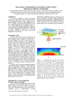
6 If a throughput of 120 beads/min in the active area. positive DEP force is induced, the cell will move towards the illumination area, while a negative DEP. response will push the cell away from the Optical pattern. Figure 2 illustrates the Sorting of HeLa Cells . The stage carrying the OET device moves from the left to the right at a constant speed of 5 flmlS. The Cells enter the active manipulation area from the left side of the screen and trigger the SLM to switch on the pixels below the Cells . The Cells experience a positive DEP. (c) 300,..-----'""1. response at an ac frequency of 100 kHz, and are pulled 250. to the bottom of the screen. The bright pixels on the SLM are turned off once the corresponding cell reaches the bottom of the screen. The trajectories of the Cells are recorded in Fig. 2(c). The linear trajectories show that the Cells experience a constant DE P force across the active area.
7 50. O 50 -1 0 0--1 5 O 2 OO 2 50 300. x posilion (!dl11. Fig. 3 (a)(b) Continuous particle Sorting on 15- and 20- pm-diameter polystyrene beads. The dashed lines show the position ofthe Optical guiding bars. (c) Trajectories of the bead entering the active area from the left of the image. (c) 12or-------, CONCLUSION. We demonstrated a fully automatic, real-time cell and microparticle Optical Sorting system that is capable of Sorting Cells based on the visual appearance. The Sorting of BeLa Cells and two sizes of latex beads has been shown. The throughput of the current system is approximately 120 Cells /min, limited by the refreshing rate of the SLM. ACKNOWLEDGMENT. X Posilion ()'Ill) The authors would like to thank the members of Prof. (a)(b) HeLa Cells concentrated at the boltom of Luke Lee's group for assistance with HeLa Cells .
8 This the images. (c) Trajectories of the HeLa Cells entering project is supported by the Institute for Cell Mimetic the active area from the leji side ofthe image_ Space Exploration (CMISE), a NASA University Research, Engineering and Technology Institute. In addition to Cells , Sorting of microparticles has REFERENCES. also been demonstrated. Figure 3 shows the Sorting of 15- and 20-!-tm-diameter polystyrene beads. The beads [1] Chiou, P. Y., Chang, Z., Wu, M. C., Optical enter the active area from the left of the screen, due to MEMS,2003. the microscope stage moving at a Velocity of 10 !-tmls. [2] Po W, H. A., Dielectrophoresis, Cambridge: Fig . 3(c) shows the particle traj ector ies of these two Cambridge University Press, 1978. sizes of particles. The 20 !-tm beads are swept to the [3] Ohta, A. T., Chiou, P. Y., Wu, M.
9 C., CLEO, 2004. bottom in the active area, while the 15 !-tm particles are [4] Chiou, P. Y., Wong, W., Liao, J. C., Wu, M. C., pushed to the top. MEMS,2004. In our current system, the throughput is limited by [5] Lu, , Huang, y'-P., Yeh, 1. A., Lee, C., Asian the refreshing rate of the SLM, which is 5 frames/so and Pacific Rim Symp. on Biophotonics, 2004. Moving the stage at a speed larger than 15 !-tmls [6] Chiou, P. Y., Ohta, A. T., Wu, M. C., MEMS, 2005. 84.