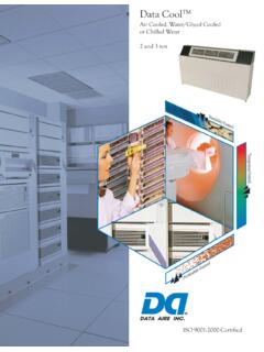
Transcription of DATA AIRE SERIES
1 DATA AIRE SERIES . Operation and Maintenance Manual DX 6-30 ton Air and Water/Glycol Cooled CONGRATULATIONS ON THE SELECTION OF A DATA AIRE PRECISION. ENVIRONMENTAL CONTROL SYSTEM. PROPER INSTALLATION, OPERATION. AND MAINTENANCE OF THIS EQUIPMENT WILL ENSURE YEARS OF OPTIMAL. PERFORMANCE. This manual is intended to assist trained service personnel by providing necessary guidelines for this particular equipment. Service to Data Aire units should be done by qualified individuals with an adequate background in areas such as HVAC, electrical, plumbing and electronics, as applicable. Service performed by unauthorized or unqualified technicians may void manufacturers' warranties and could result in property damage and/or personal injury. Special care should be given to those area where these symbols appear. Data Aire, Inc. reserves the right to make design changes for the purposes of product improvement, or to withdraw any design without notice.
2 2. Table of Contents INSTALLATION .. 6. Room Considerations .. 6. Inspection .. 6. Rigging .. 6. Locating the Unit .. 7. Downflow 7. Upflow Units .. 8. Paperwork .. 8. Storage .. 8. PIPING .. 9. Air Cooled Unit Piping .. 9. Discharge 9. Liquid Lines .. 9. Suction Lines .. 10. Connection Sizes, Air Cooled 10. Field Piping, Remote Condenser .. 10. Field Piping, Remote Condensing Unit ..11. Water/Glycol Cooled Unit Piping ..11. Field Piping, Glycol 12. Connection Sizes, Water/Glycol Cooled Units .. 12. Connection Sizes, Fluid Coolers .. 12. Auxiliary Chilled Water Coil Piping .. 13. Condensate Drain Piping .. 13. Humidifier Piping .. 13. Steam Generator 13. Dry Steam Humidifier .. 13. Leak Testing .. 14. 14. ELECTRICAL CONNECTIONS .. 15. Electrical .. 15. Nameplate Ratings .. 15. 15. Voltage Tolerance .. 15. Auxiliary Control Wiring .. 15. Remote Shutdown .. 15. Remote Alarm Contacts .. 16. Remote 16. Condensate Pumps .. 16. Condensate Probe.
3 17. Water Sensing Cable .. 17. 3. Table of Contents, cont'd INSTALLATION OF REMOTE HEAT EXCHANGER .. 18. Rigging .. 18. Leg Assembly .. 18. Locating the Remote Heat Exchanger .. 18. Electrical Service .. 19. Air Cooled Condensers - Model DARC .. 19. Fan Speed Control .. 19. Ambient Thermostats .. 19. Fluid Coolers - Model DAFC .. 20. Fluid-Sensing Thermostats .. 20. Energy Saver Cooling .. 20. CHARGING .. 21. Voltage Phase Check .. 21. Evaporator .. 21. Secondary Heat Exchanger .. 21. Important Refrigeration Components .. 21. Expansion Valve .. 21. High Pressure Cutout Switch .. 21. Low Pressure Cutout Switch .. 22. Air Cooled Systems .. 22. Fan Speed Control System 22. Flooded System Charging .. 23. Water/Glycol Cooled Systems .. 24. Water/Glycol Cooled Systems Charging .. 24. Refrigerant Handling .. 24. GLYCOL SYSTEMS .. 25. Glycol Concentration .. 25. Internal (Fluid) Volume - Downflow Models .. 25. Internal (Fluid) Volume - Upflow Models.
4 25. Fluid Cooler Internal Volume .. 26. Copper Piping Internal 26. Freezing Point of Aqueous Solutions .. 26. CONTROLS .. 27. DAP III Microprocessor Control Panel .. 27. Secondary Heat 27. Wiring Diagrams .. 27. 4. Table of Contents, cont'd REGULAR MAINTENANCE ITEMS .. 28. 28. Belts .. 28. Bearings .. 28. Humidifier Canisters .. 28. 29. Heating Elements .. 29. Refrigerant Filter Drier .. 29. WARRANTY .. 30. CONTACT DATA AIRE .. 31. LINE SIZING CHART .. 32. MONTHLY MAINTENANCE INSPECTION CHECKLIST .. 33. QUARTERLY MAINTENANCE INSPECTION 34. SUPERHEAT and SUCTION PRESSURE TROUBLE SHOOTING GUIDE .. 35. TEMPERATURE PRESSURE 36. CORRECTION FACTOR FOR SUPERHEAT 37. 38, 39. 5. INSTALLATION. There is no intent on the part of Data Aire, Inc. to define local codes or statutes which may supersede common trade practices. The manufacturer assumes no responsibility for their interpretation. Consult local building codes and the National Electrical Code for special installation requirements.
5 Room Considerations Precision air conditioning equipment is designed to control spaces within close tolerances of temperature and humidity. However, the room must be built with a proper vapor barrier. A film of polyethylene is often used on walls and ceilings. Walls and floors must also be painted with a vapor- seal paint. Failure to provide a vapor barrier can compromise space conditions. Introduction of outside air into the space should be minimized. Outside air in excess of 5% of the total circulated air volume can have a significant effect on the overall space conditions and result in poor space control. Inspection This Data Aire unit has been factory run-tested and has gone through a comprehensive inspection prior to its packaging and shipment to ensure that it arrives in excellent condition. However, shipping damage can occur and a visual inspection of the outer crating immediately upon delivery should be performed. Note any external damage or other transportation damage on the freight carrier's forms.
6 Inspect the unit itself for internal damage. A claim should be filed with the shipping company if the equipment is damaged or incomplete. Loose items such as remote control panels, disconnect switch handles, spare belts and spare filters are packed inside the unit. Refer to the yellow shipping tag located on the unit door for details. Freight damage claims are the responsibility of the purchaser. Action to recover losses should be filed immediately. Please notify factory personnel of any claims. Rigging Move the unit in its upright position to the installation site. It is recommended that the unit be protected from damage to the decorative doors during any storage or moving. Removal of the decorative doors is easily accomplished and may be done when moving equipment. The shipping skid should be left in place if the unit is being moved with a forklift. If the unit is being lifted, use spreader bars to prevent damage to the doors and panels.
7 The unit has 3/4 holes in the shipping skid to which casters with 3/4 stems can be attached. This allows easy movement down halls, into elevators and through doorways. If clearance is a problem 6. the casters may be inserted directly into the bottom of the 1 tubular steel corner posts at the bottom of the unit. Warning: Improper lifting or moving of equipment may result in damage to decorative doors, panels or frame members. Locating the Unit When installing the unit, sufficient space must be allowed for airflow clearance, wiring, plumbing, and service access. It is recommended that each side and front have a clearance of at least 30 to allow the doors to swing open and for servicing the unit. The doors on some sides may not require as much service clearance. Refer to the particular unit component breakdown drawings for assistance. Rear clearance is not required, but 1 to 2 of clearance is suggested. For the best air distribution, the unit should be centered against the longest wall, as close to the heat load as possible, unless the unit is ducted.
8 The unit should not be placed near any corner of the room or at the end of a long, narrow room. Multiple units should be evenly spaced, as far apart as possible. Note to Installing Contractor: Condensation formation and frequent humidifier flushing are normal functions of this equipment. Proper drain connections must be made to ensure proper removal. Unit will require water connections for condensate removal and possibly for humidifier makeup water, condenser water, chilled water and/or hot water. Installation of units above equipment that could sustain water damage should be avoided. Downflow Units Downflow units will typically sit on an elevated flooring system known as a raised floor. The unit discharges air downward which pressurizes the raised floor and channels upward through perforated floor tiles. Location and quantity of perforated tiles will dictate proper air distribution. If the raised floor is strong enough to support the unit and local codes permit, the unit can be placed directly on top with cutouts made for the discharge openings.
9 There may be additional support required in the form of adjustable jackstands. These are adjustable, threaded leveling rods which support the unit in each of the corners and in the center on longer length units. Tighten the locknuts provided with each jackstand. The baseplate can rest on the floor or on vibration isolation pads. Floorstands are also a way of supporting the unit. These are ordered to the height of the floor with leveling rods to allow adjustment. The floorstand has lips in each corner to align with the unit which is placed on top. It is recommended that the unit frame be bolted or screwed to the floorstand from below. Local building codes may dictate this procedure. After installation, the raised floor is typically built around the unit. The raised floor serves as the distribution plenum for air on downflow units. Cables, piping, wiring raceways, inadequate floor height and any other restrictions can inhibit proper airflow.
10 Care should be taken to avoid restrictions. 7. Upflow Units Upflow units will typically be supported by vibration isolation pads and/or floorstands which may also include leveling screws. An air discharge plenum may be factory provided which ships loose and must be attached at the top of the unit frame. Alternately, an air distribution plenum must be field fabricated with supply grilles to distribute the air. Units are shipped with a drive package to overcome external static pressure. Adjustments to the blower speed may be required to adjust to actual conditions. Paperwork Each Data Aire unit ships with a start-up sheet that should be completed during installation. Also included in the paperwork is a warranty/information packet that provides important wiring diagrams, specific component literature, warranty registration cards and other valuable paperwork, including a copy of this Installation/Operation and Maintenance manual. A yellow tag is attached to the outside decorative door to indicate articles that may have been packaged and shipped loose within the unit cabinet.