Transcription of DB101 THRU DB107 SINGLE-PHASE GLASS …
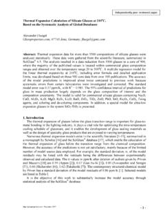
1 MAXIMUM RATINGS AND ELECTRICAL CHARACTERISTICSR atings at 25 oC ambient temperature unless otherwise or inductive THRUDB107DB-1 Dimensions in inches and (millimeters)FEATURES* Good for automation insertion*Surge overload rating - 40 amperes peak* Ideal for printed circuit board* Reliable low cost construction utilizing molded* GLASS passivated device*Polarity symbols molded on body*Mounting position: Any* Weight: gram* Epoxy: Device has UL flammability classification 94V-OMECHANICAL DATAMAXIMUM RATINGS (At TA = 25oC unless otherwise noted)ELECTRICAL CHARACTERISTICS (At TA = 25oC unless otherwise noted)2011-04 REV:BRATINGSM aximum Recurrent Peak Reverse VoltageMaximum RMS Bridge Input VoltageMaximum DC Blocking VoltagePeak Forward Surge Current ms single half sine-wavesuperimposed on rated load (JEDEC method)Operating and Storage Temperature RangeSYMBOLVRRMVDCIOIFSMI2t TJ, to + 1500 CUNITSM aximum Average Forward Output Current at TA = 40oC502004001006008001000351402807042056 0700 VoltsAmpsA2/SecDB101DB103DB104DB102DB105 DB106DB107DB101DB103DB104DB102DB105DB106 DB107502004001006008001000DC Blocking Voltage per at DCMaximum Forward Voltage Drop per BridgeVolts@TA = 25oC@TA = Thermal Resistance (Note 2)Current Squarad TimeNote: 1.
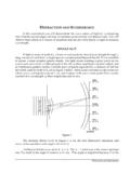
2 Fully ROHS compliant , 100% Sn plating(Pb-free).2. Thermal Resistance: PCB Reverse Current at RatedSINGLE-PHASE GLASS PASSIVATEDSILICON BRIDGE ( ) .060( ).020( ).195 ( ) .165 ( ) .155 ( ) .135 ( ) .115 ( ) .335 ( ) .320 ( ) .350 ( ) .300 ( ) .255 ( ) .245 ( ) * UL listed under the recognized component directory, file # RANGE 50 to 1000 Volts CURRENT Ampere 3. Available in Halogen-free epoxy by adding suffix -HF after the part FORWARD VOLTAGE, (V)INSTANTANEOUS FORWARD CURRENT, (A) FORWARD CURRENT, (A) AND CHARACTERISTICS CURVES ( DB101 THRU DB107 ) TYPICAL INSTANTANEOUS FORWARD CHARACTERISTICSAMBIENT TEMPERATURE, (OC) TYPICAL FORWARD CURRENT DERATING CURVENUMBER OF CYCLES AT 60 HzPEAK FORWARD SURGE CURRENT, (A) single Half Sine-WaveJEDEC MethodFIG. 1 - MAXIMUM NON-REPETITIVE FORWARD SURGE CURRENT TJ = 25 OCPulse Width = 300mS1% Duty Cycle60 Hz RESISTIVE OR INDUCTIVE LOADPERCENT RATED PEAK REVERSE VOLTAGE, (%) TYPICAL REVERSE CHARACTERISTICSINSTANTANEOUS REVERSE CURRENT, (uA)TA = 25 OCTA = 125 OCTHE MARKING OF DB10 XMarking Description :V Y W WDB10 XYear CodeWeek CodePart No.
3 Marking Description D B 1 0 X Rectron Logo Part code (Y:Last digit of year) Week code (WW:01~52) Voltage-code 1-------50V 5-------600V 2-------100V 6-------800V 3-------200V 7-----1000V 4-------400V ~ ~ V Y W W + - PACKAGING OF DIODE AND BRIDGE RECTIFIERSTUBE PACKPACKAGEDB-12,500450*140*84464*305*28 315, PER BOXINNER BOX SIZE(mm)CARTON SIZE(mm)EA PER CARTONWEIGHT(Kg)PACKING CODE-C Rectron Inc reserves the right to make changes without notice to any product specification herein, to make corrections, modifications, enhancements or other changes. Rectron Inc or anyone on its behalf assumes no responsibility or liabi- lity for any errors or inaccuracies.
4 Data sheet specifications and its information contained are intended to provide a product description only. "Typical" paramet- ers which may be included on RECTRON data sheets and/ or specifications ca- n and do vary in different applications and actual performance may vary over ti- me. Rectron Inc does not assume any liability arising out of the application or use of any product or circuit. Rectron products are not designed, intended or authorized for use in medical, life-saving implant or other applications intended for life-sustaining or other rela- ted applications where a failure or malfunction of component or circuitry may di- rectly or indirectly cause injury or threaten a life without expressed written appr- oval of Rectron Inc.
5 Customers using or selling Rectron components for use in such applications do so at their own risk and shall agree to fully indemnify Rect- ron Inc and its subsidiaries harmless against all claims, damages and expendit- ures. DISCLAIMER NOTICE