Transcription of Dell OptiPlex 3060 Micro Service Manual
1 dell OptiPlex 3060 MicroService ManualRegulatory Model: D10 URegulatory Type: D10U003 September 2021 Rev. A02 Notes, cautions, and warningsNOTE: A NOTE indicates important information that helps you make better use of your : A CAUTION indicates either potential damage to hardware or loss of data and tells you how to avoidthe : A WARNING indicates a potential for property damage, personal injury, or death. 2016 - 2020 dell Inc. or its subsidiaries. All rights reserved. dell , EMC, and other trademarks are trademarks of dell Inc. or its trademarks may be trademarks of their respective 1: Working on your 5 Safety 5 Turning off your computer Windows working inside your working inside your 2: Technology and 7 USB 8 HDMI 10 Chapter 3: Removing and installing 12 Recommended 12 Screw size 12 Micro Motherboard 14 Removing side 14 Installing side 15 Hard drive 17 Removing inch hard drive 17 Removing the inch drive from the drive 17 Installing the inch hard drive into the drive 18 Installing inch drive heat sink 19 Installing heat sink 22 Removing 22 Installing 23 Memory 24 Removing memory 24 Installing memory 25 Heat sink.
2 26 Removing 26 Installing 28 Removing 28 Installing 29 WLAN the WLAN the WLAN PCIe the PCIe SSD ..34 ContentsContents3 Installing the PCIe SSD ..35 Optional 36 Removing optional 36 Installing optional 38 Coin-cell 39 Removing coin cell coin cell 40 System 41 Removing system 41 Installing system 4: 46 dell SupportAssist Pre-boot System Performance Check the SupportAssist Pre-Boot System Performance Unit Built-in Self-Test .. 47 Diagnostic error 49 System error 51 Recovering the operating 52 Backup media and recovery Clock (RTC Reset)..52 WiFi power 53 Chapter 5: Getting 544 ContentsWorking on your computerTopics: Safety instructions Turning off your computer Windows 10 Before working inside your computer After working inside your computerSafety instructionsPrerequisitesUse the following safety guidelines to protect your computer from potential damage and to ensure your personal safety.
3 Unlessotherwise noted, each procedure included in this document assumes that the following conditions exist: You have read the safety information that shipped with your computer. A component can be replaced or, if purchased separately, installed by performing the removal procedure in reverse this taskWARNING: Before working inside your computer, read the safety information that shipped with your additional safety best practices information, see the Regulatory Compliance HomepageCAUTION: Many repairs may only be done by a certified Service technician. You should only performtroubleshooting and simple repairs as authorized in your product documentation, or as directed by the online ortelephone Service and support team. Damage due to servicing that is not authorized by dell is not covered byyour warranty.
4 Read and follow the safety instructions that came with the : To avoid electrostatic discharge, ground yourself by using a wrist grounding strap or by periodicallytouching an unpainted metal surface at the same time as touching a connector on the back of the : Handle components and cards with care. Do not touch the components or contacts on a card. Hold acard by its edges or by its metal mounting bracket. Hold a component such as a processor by its edges, not byits : When you disconnect a cable, pull on its connector or on its pull-tab, not on the cable itself. Somecables have connectors with locking tabs; if you are disconnecting this type of cable, press in on the lockingtabs before you disconnect the cable. As you pull connectors apart, keep them evenly aligned to avoid bendingany connector pins.
5 Also, before you connect a cable, ensure that both connectors are correctly oriented : Disconnect all power sources before opening the computer cover or panels. After you finish working inside thecomputer, replace all covers, panels, and screws before connecting to the power : Exercise caution when handling Lithium-ion batteries in laptops. Swollen batteries should not be usedand should be replaced and disposed : The color of your computer and certain components may appear differently than shown in this on your computer5 Turning off your computer Windows 10 About this taskCAUTION: To avoid losing data, save and close all open files and exit all open programs before you turn off yourcomputer or remove the side or tap . or tap and then click or tap Shut : Ensure that the computer and all attached devices are turned off.
6 If your computer and attached devices did notautomatically turn off when you shut down your operating system, press and hold the power button for about 6 secondsto turn them working inside your and close all open files and exit all open down your computer. Click Start > Power > Shut : If you are using a different operating system, see the documentation of your operating system for your computer and all attached devices from their electrical all attached network devices and peripherals, such as keyboard, mouse, and monitor from your any media card and optical disc from your computer, if the computer is unplugged, press and hold the power button for 5 seconds to ground the system : Place the computer on a flat, soft, and clean surface to avoid scratches on the the computer face working inside your computerAbout this taskNOTE.
7 Leaving stray or loose screws inside your computer may severely damage your all screws and ensure that no stray screws remain inside your any external devices, peripherals, or cables you removed before working on your any media cards, discs, or any other parts that you removed before working on your your computer and all attached devices to their electrical on your on your computerTechnology and componentsThis chapter details the technology and components available in the : Processors DDR4 USB features HDMI 5060 systems are shipped with Intel 8th generation-Coffee Lake chipset and core processor : The clock speed and performance varies depending on the workload and other variables. Total cache up to 8 MBcache depending on processor type. Intel Pentium Gold G5400 (2 Cores/4MB/4 ); supports Windows 10/Linux Intel Pentium Gold G5500 (2 Cores/4MB/4 ); supports Windows 10/Linux Intel Core i3-8100 (4 Cores/6MB/4 ); supports Windows 10/Linux Intel Core i3-8300 (4 Cores/8MB/4 ); supports Windows 10/Linux Intel Core i5-8400 (6 Cores/9MB/6T/up to ); supports Windows 10/Linux Intel Core i5-8500 (6 Cores/9MB/6T/up to ); supports Windows 10/Linux Intel Core i5-8600 (6 Cores/9MB/6T/up to ); supports Windows 10/Linux Intel Core i7-8700 (6 Cores/12MB/12T/up to ); supports Windows 10/LinuxDDR4 DDR4 (double data rate fourth generation) memory is a higher-speed successor to the DDR2 and DDR3 technologies and allowsup to 512 GB in capacity, compared to the DDR3's maximum of 128 GB per DIMM.
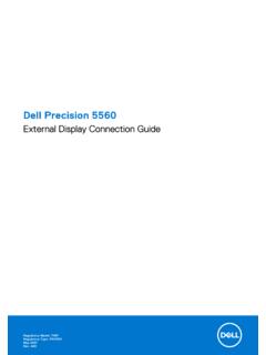
8 DDR4 synchronous dynamic random-accessmemory is keyed differently from both SDRAM and DDR to prevent the user from installing the wrong type of memory into needs 20 percent less or just volts, compared to DDR3 which requires volts of electrical power to operate. DDR4also supports a new, deep power-down mode that allows the host device to go into standby without needing to refresh itsmemory. Deep power-down mode is expected to reduce standby power consumption by 40 to 50 DetailsThere are subtle differences between DDR3 and DDR4 memory modules, as listed notch differenceThe key notch on a DDR4 module is in a different location from the key notch on a DDR3 module. Both notches are on theinsertion edge but the notch location on the DDR4 is slightly different, to prevent the module from being installed into anincompatible board or and components7 Figure 1.
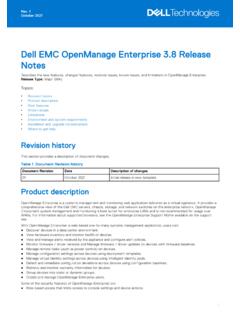
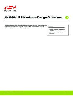
9 Notch differenceIncreased thicknessDDR4 modules are slightly thicker than DDR3, to accommodate more signal 2. Thickness differenceCurved edgeDDR4 modules feature a curved edge to help with insertion and alleviate stress on the PCB during memory 3. Curved edgeMemory ErrorsMemory errors on the system display the new ON-FLASH-FLASH or ON-FLASH-ON failure code. If all memory fails, the LCDdoes not turn on. Troubleshoot for possible memory failure by trying known good memory modules in the memory connectors onthe bottom of the system or under the keyboard, as in some portable : The DDR4 memory is imbedded in board and not a replaceable DIMM as shown and featuresUniversal serial Bus, or USB, was introduced in 1996. It dramatically simplified the connection between host computers andperipheral devices like mice, keyboards, external drivers, and 1.
10 USB evolution TypeData Transfer RateCategoryIntroduction YearUSB MbpsHigh Speed20008 Technology and componentsTable 1. USB evolution (continued)TypeData Transfer RateCategoryIntroduction YearUSB Gen15 GbpsSuperSpeed2010 USB Gen 210 GbpsSuperSpeed2013 USB Gen 1 (SuperSpeed USB)For years, the USB has been firmly entrenched as the de facto interface standard in the PC world with about 6 billiondevices sold, and yet the need for more speed grows by ever faster computing hardware and ever greater bandwidth USB Gen 1 finally has the answer to the consumers' demands with a theoretically 10 times faster than itspredecessor. In a nutshell, USB Gen 1 features are as follows: Higher transfer rates (up to 5 Gbps) Increased maximum bus power and increased device current draw to better accommodate power-hungry devices New power management features Full-duplex data transfers and support for new transfer types Backward USB compatibility New connectors and cableThe topics below cover some of the most commonly asked questions regarding USB Gen , there are 3 speed modes defined by the latest USB Gen 1 specification.