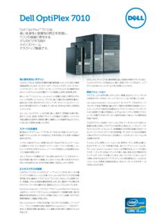
Transcription of DELL™ OPTIPLEX™ 7010 TECHNICAL GUIDEBOOK …
1 dell optiplex 7010 TECHNICAL GUIDEBOOK dell TM. optiplex 7010. TM. TECHNICAL GUIDEBOOK . INSIDE THE optiplex 7010. 1. TABLE OF CONTENTS. OVERVIEW. Mini Tower Computer (MT) View 3-4. Desktop Computer (DT) View 5-6. Small Form Factor Computer (SFF) View 7-8. 9-10. Ultra Small Form Factor Computer (USFF) View MARKETING SYSTEM CONFIGURATIONS. Operating System, Chipset 11. Processor 12. Memory 13. Drives and Removable Storage, 14. System Board Connectors 15. Graphics/Video Controller 16. External Ports/Connectors 16. Communications Network Adapter (NIC), Wireless 17. Audio and Speakers, Keyboard and Mouse 17. Security, Service and Support, Software 18.
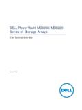
2 DETAILED ENGINEERING SPECIFICATIONS. System Dimensions (Physical) 19. System Board Connector Maximum Allowable Dimensions 19. System Level Environmental and Operating Conditions 20. Power 21-22. Audio 23. Communications 23-28. Graphics/Video Controller 29-30. Hard Drives 31-38. Optical Drive 39-40. Media Card Reader 41. BIOS Defaults 42. Chassis Enclosure and Ventilation Requirements 43. Acoustic Noise Emission Information 44-47. dell optiplex 7010 TECHNICAL GUIDEBOOK MINI TOWER COMPUTER (M T) VI EW. FRONT VIEW BACK VIEW. 1 Power Button, Power 6 Optical Drive (optional) 10 Power Supply Diag- 14 Expansion Card Slots Light nostic Light (4).
3 2 Optical Drive Bay 7 Optical Drive Eject 11 Power Supply Diag- 15 kensington / Noble (optional) Button nostic Button Security Cable Slot 3 Headphone Connector 8 USB Connectors (2). 12 Power Connectors 16 Padlock Ring 4 Microphone 9 Drive Activity Light Connector 13 Back Panel Connect- 5 USB Connectors ors (2). BACK PANEL CONNECTORS. PS2 Mouse Con- SP2 Keyboard Con- 1 7. nector nector 2 Link Integrity Light 8 Connectors (2). DisplayPort Connector 3 Network Connector 9. (2). Network Activity Connectors (2). 4 10. Light Connectors (2). 5 Serial Connector 11 VGA Connector Line-in/Microphone 6 Line-out Connector 12. Connector 3.
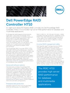
4 dell optiplex 7010 TECHNICAL GUIDEBOOK MT System Board Components Num- Num- Name Name ber ber 1 Internal Speaker Connector (INT_SPKR) 13 PCI-e x16 (wire x4) Connector (SLOT4). 2 Front IO Connector (FRONTPANEL) 14 Buzzer (BEEP). 3 Thermal Sensor Connector (THRM_2) 15 LPC Debug Connector (LPC_DEBUG). 4 SATA 0 Connector (SATA0) 16 Intrusion Switch Connector (INTRUDER). 5 SATA 1 Connector (SATA1) 17 System Fan Connector (FAN_HDD). 6 SATA 2 Connector (SATA2) 18 P2 Power Connector (12V_PWRCONN). 7 SATA 3 Connector (SATA3) 19 Processor Socket (N/A). 8 Internal USB Connector (INT_USB) 20 CPU fan Connector (FAN_CPU). Memory Connectors (DIMM1, DIMM2, 9 Battery Connector (BATTERY) 21.)
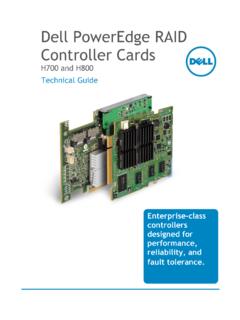
5 DIMM3, DIMM4). 10 PCI-e x16 Connector (SLOT1) 22 Power Switch Connector (PWR_SW). 11 PCI-e x1 Connector (SLOT2) 23 P1 Power Connector (POWER). 12 PCI Connector (SLOT3) 24 Front Connector (Front _USB ). 4. dell optiplex 7010 TECHNICAL GUIDEBOOK D ESK TOP COMP UT ER (D T) VIEW. FRONT VIEW BACK VIEW. Expansion Card Slots 1 Optical Drive 5 USB Connectors (2) 9 Padlock Ring 13. (4). Optical Drive Eject 2 6 Microphone Connector 1 kensington / Noble 14. Power Supply Button 0 Security Cable Slot Diagnostic Light Power Button, Power Power Supply 3 7 Headphone Connector 11 Power Connectors 15. Light Diagnostic Button 4 USB Connectors (2) 8 Drive Activity Light 1 Back Panel 2 Connectors BACK PANEL CONNECTORS.
6 PS2 Mouse PS2 Keyboard 1 7. Connector Connector 2 Link Integrity Light 8 Connectors (2). DisplayPort Connector 3 Network Connector 9. (2). Network Activity Connectors (2). 4 10. Light Connectors (2). 5 Serial Connector 11 VGA Connector Line-in/Microphone 6 Line-out Connector 12. Connector 5. dell optiplex 7010 TECHNICAL GUIDEBOOK DT System Board Components Num- Num- Name Name ber ber 1 Internal Speaker Connector (INT_SPKR) 12 PCI-e x16 (wire x4) Connector (SLOT4). 2 Front IO Connector (FRONTPANEL) 13 Buzzer (BEEP). 3 Thermal Sensor Connector (THRM_2) 14 LPC Debug Connector (LPC_DEBUG). 4 SATA 0 Connector (SATA0) 15 Intrusion Switch Connector (INTRUDER).
7 5 SATA 1 Connector (SATA1) 16 System Fan Connector (FAN_HDD). 6 SATA 2 Connector (SATA2) 17 P2 Power Connector (12V_PWRCONN). 7 Internal USB Connector (INT_USB) 18 Processor Socket (N/A). 8 Battery Connector (BATTERY) 19 CPU fan Connector (FAN_CPU). Memory Connectors (DIMM1, DIMM2, 9 PCI-e x16 Connector (SLOT1) 20. DIMM3, DIMM4). 10 PCI-e x1 Connector (SLOT2) 21 Power Switch Connector (PWR_SW). 11 PCI Connector (SLOT3) 22 P1 Power Connector (POWER). 23 Front Connector (Front _USB ). 6. dell optiplex 7010 TECHNICAL GUIDEBOOK SM ALL FORM F ACTOR COMP UTER (SF F ) VIEW. FRONT VIEW BACK VIEW. 9 Padlock Ring 13 Power Supply 1 Optical Drive 5 USB Connectors (2).
8 Diagnostic Light 2 Optical Drive Eject 6 Microphone Connector 10 kensington / Noble 14 Back Panel Button Security Cable Slot Connectors 3 Power Button, Power 7 Headphone Connector 11 Power Connectors 15 Expansion Card Slots Light (2). 4 USB Connectors (2) 8 Drive Activity Light 12 Power Supply Diagnostic Button BACK PANEL CONNECTORS. 1 PS2 Mouse 7 PS2 Keyboard Connector Connector 2 Serial Connector 8 VGA Connector 3 Link Integrity Light 9 DisplayPort Connector(2). 4 Network Connector 10 USB Connectors (2). 5 Network Activity Light Connectors (2). 11. Connectors (2). 6 Line-out Connector 12 Line-in/Microphone Con- nector 7.
9 dell optiplex 7010 TECHNICAL GUIDEBOOK SFF System Board Components Number Name Number Name 1 P1 power Connector (POWER) 11 Front IO Connector (FRONTPANEL). 2 System fan Connector (FAN_HDD) 12 Intrusion Switch Connector (INTRUDER). 3 Internal Speaker Connector (INT_SPKR) 13 LPC debug Connector (LPC_DEBUG). 4 Buzzer (BEEP) 14 Battery Connector (BATTERY). 5 PCI-e x16 (wire x4) Connector (SLOT2) 15 P2 Power Connector (12V_PWRCONN). 6 PCI-e x16 Connector (SLOT1) 16 Processor Connector (N/A). 7 Front Connector (Front _USB ) 17 CPU Fan Connector (FAN_CPU). 8 SATA 2 Connector (SATA2) 18 Power Switch Connector (PWR_SW). 9 SATA 1 Connector (SATA1) 19 Memory Connectors (DIMM1, DIMM2, DIMM3, DIMM4).
10 10 SATA 0 Connector (SATA0). 8. dell optiplex 7010 TECHNICAL GUIDEBOOK UL TR A SMALL FO RM F ACTO R COMP UTER (U SFF ) VIEW. FRONT VIEW BACK VIEW. 1 Optical Drive 5 Headphone Connector Wi-Fi Antenna Line-in/ Microphone 8 15. (optional) Connector 2 Optical Drive Eject 6 Microphone Connector VGA Connector 9 Network Activity Light 16. Button 3 Power Button, Power 7 USB Connectors (2) DisplayPort Connector 10 Captive Thumbscrew 17. Light (2). 11 Padlock Ring 18 Serial Connector 4 Drive Activity Light kensington / Noble USB Connectors 12 19. Security Cable Slot (2). USB Connectors 13 Power Connector 20. (2). 14 Line-Out Connector 21 Network Connector 22 Link Integrity Light 9.