Transcription of DELL TM
1 TECHNICAL GUIDEBOOK INSIDE THE optiplex 3010 TM dell optiplex 3010TM TABLE OF CONTENTS OVERVIEW Mini Tower Computer (MT) View 3-4 Desktop Computer (DT) View 5-6 Small Form Factor Computer (SFF) View 7-8 MARKETING SYSTEM CONFIGURATIONS Operating System, Chipset 9 Processor 10 Memory 11 Hard Drives, Removable Storage, System Expansion Slots 12 Graphics/Video Controller, External Ports/Connectors 13 Communications Network Adapter (NIC), Wireless 14 Audio and Speakers, Keyboard and Mouse 14 Security HW & SW, Environmental, All-in-One Stands & Mounts, Service and Support 15 DETAILED ENGINEERING SPECIFICATIONS System Dimensions (Physical) 16 System Expansion Slots 16 System Level Environmental and Operating Conditions 17 Power 18-19 Audio 20 Communications 20-25 Graphics/Video Controller 26-27 Hard Drives 28-30 Optical Drive 31-32 Media Card Reader 33 BIOS Defaults 34 Chassis Enclosure and Ventilation Requirements 35 Acoustic Noise Emission Information 36-38 dell optiplex 3010 TECHNICAL GUIDEBOOK FINAL 3 MINI TOWER COMPUTER (MT)
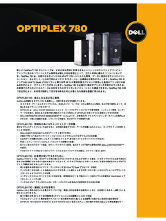
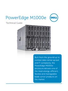
2 VIEW 2 3 4 5 6 7 8 9 1 10 11 12 13 14 15 16 FRONT VIEW 1 Power Button, Power Light 6 Optical Drive (optional) 2 Optical Drive Bay (optional) 7 Optical Drive Eject Button 3 Microphone Connector 8 USB Connectors (2) 4 Headphone Connector 9 Drive Activity Light 5 Diagnostic Lights (4) BACK VIEW 10 Power Supply Diagnostic Light 14 Expansion Card Slots(4) 11 Power Supply Diagnostic Button 15 Security Cable Slot 12 Power Connectors 16 Padlock Ring 13 Back Panel Connectors 1 2 3 4 5 6 7 8 9 BACK PANEL CONNECTORS 1 Link Integrity Light 6 VGA Connector 2 Network Connector 7 Line-in Connector 3 Network Activity Light 8 Line-out Connector 4 USB Connectors (6) 9 Microphone Connector 5 HDMI Connector dell optiplex 3010 TECHNICAL GUIDEBOOK FINAL 4 Number Name Number Name 1 Front IO connector (FRONTPANEL)) 14 PCI-e 16x Connector (SLOT1) 2 Internal Speaker Connector (INT_SPKR) 15 System fan Connector (FAN_SYS2) 3 System fan Connector (FAN_SYS1)
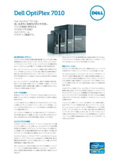
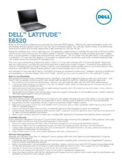
3 16 P2 Power Connector(ATX12V) 4 SATA 1 Connector(SATA1) 17 CPU Socket Connector (U27 CPU) 5 SATA 0 Connector(SATA0) 18 CPU fan Connector (FAN_CPU) 6 SATA 2 Connector(SATA2) 19 Memory Connector(DIMM1) 7 SATA 3 Connector(SATA3) 20 P1 power Connector (ATX) 8 Internal USB Connector (USBF1) 21 Power Switch Connector (PWRSW1) 9 Internal USB Connector (USBF1) 22 Memory Connector(DIMM2) 10 Internal Audio Connector (AUDIOF1) 23 Battery Connector (BT1) 11 PCI-e 1x Connector (SLOT4) 24 Intrusion Switch Connector (Intruder) 12 PCI-e 1x Connector (SLOT3) 25 KB/MS COM Connector (KBMSCOM1) 13 PCI-e 1x Connector (SLOT2) MT System Board Components dell optiplex 3010 TECHNICAL GUIDEBOOK FINAL 5 DESKTOP COMPUTER (DT) VIEW FRONT VIEW 1 Optical Drive 5 Microphone Connector 2 Optical Drive Eject Button 6 Headphone Connector 3 Power Button, Power Light 7 Drive Activity Light 4 USB Connectors (2) 8 Diagnostic Lights (4) BACK VIEW 9 Padlock Ring 13 Expansion Card Slots(4)
4 10 Security Cable Slot 14 Power Supply Diagnostic Light 11 Power Connectors 15 Power Supply Diagnostic Button 12 Back Panel Connectors BACK PANEL CONNECTORS 1 Link Integrity Light 6 VGA Connector 2 Network Connector 7 Line-in Connector 3 Network Activity Light 8 Line-out Connector 4 USB Connectors (6) 9 Microphone Connector 5 HDMI Connector 1 2 3 4 5 6 7 8 9 10 11 12 13 14 15 1 2 3 4 5 6 7 8 9 dell optiplex 3010 TECHNICAL GUIDEBOOK FINAL 6 DT System Board Components Number Name Number Name 1 Front IO connector (FRONTPANEL)) 14 PCI-e 16x Connector (SLOT1) 2 Internal Speaker Connector (INT_SPKR) 15 System fan Connector (FAN_SYS2) 3 System fan Connector (FAN_SYS1) 16 P2 Power Connector(ATX12V) 4 SATA 1 Connector(SATA1) 17 CPU Socket Connector (U27 CPU) 5 SATA 0 Connector(SATA0) 18 CPU fan Connector (FAN_CPU) 6 SATA 2 Connector(SATA2) 19 Memory Connector(DIMM1) 7 SATA 3 Connector(SATA3) 20 P1 power Connector (ATX) 8 Internal USB Connector (USBF1) 21 Power Switch Connector (PWRSW1) 9 Internal USB Connector (USBF1) 22 Memory Connector(DIMM2) 10 Internal Audio Connector (AUDIOF1) 23 Battery Connector (BT1) 11 PCI-e 1x Connector (SLOT4) 24 Intrusion Switch Connector (Intruder) 12 PCI-e 1x Connector (SLOT3)
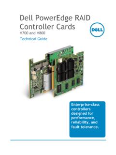
5 25 KB/MS COM Connector (KBMSCOM1) 13 PCI-e 1x Connector (SLOT2) dell optiplex 3010 TECHNICAL GUIDEBOOK FINAL 7 SMALL FORM FACTOR COMPUTER (SFF) VIEW FRONT VIEW 1 Optical Drive 5 Microphone Connector 2 Optical Drive Eject Button 6 Headphone Connector 3 Power Button, Power Light 7 Diagnostic Lights (4) 4 USB Connectors (2) 8 Drive Activity Light BACK VIEW 9 Padlock Ring 13 Power Supply Diagnostic Light 10 Security Cable Slot 14 Back Panel Connectors 11 Power Connectors 15 Expansion Card Slots(2) 12 Power Supply Diagnostic Button BACK PANEL CONNECTORS 1 HDMI Connector 5 Link Integrity Light 2 VGA Connector 6 Network Connector 3 USB Connectors (6) 7 Network Activity Light 4 Line-in/Microphone Connector 8 Line-out Connector 1 2 3 4 5 6 7 8 9 10 11 14 15 12 13 5 6 7 3 1 8 2 4 dell optiplex 3010 TECHNICAL GUIDEBOOK FINAL 8 Number Name Number Name 1 P1 power Connector (ATX) 12 KB/MS COM Connector (KBMSCOM1) 2 System fan Connector (FAN_SYS) 13 Battery Connector (BT1) 3 Internal Speaker Connector (INT_SPKR) 14 P2 Power Connector(ATX12V) 4 Front IO connector (FRONTPANEL) 15 CPU Socket Connector (U27 CPU)
6 5 Internal USB Connector (USBF1) 16 CPU fan Connector (FAN_CPU) 6 PCI-e 16x Connector (SLOT1) 17 Memory Connector(DIMM1) 7 PCI-e 1x Connector (SLOT2) 18 Memory Connector(DIMM2) 8 Internal Audio Connector (AUDIOF1) 19 Power Switch Connector (PWRSW1) 9 SATA 0 Connector(SATA0) 10 SATA 1 Connector (SATA1) 11 Intrusion Switch Connector (Intruder) SFF System Board Components dell optiplex 3010 TECHNICAL GUIDEBOOK FINAL 9 MARKETING SYSTEM CONFIGURATIONS NOTE: Offerings may vary by country. For more information regarding the configuration of your computer, click Start>Help and Support and select the option to view information about your computer.
7 OPERATING SYSTEM MT DT SFF Windows 7 operating system Microsoft Windows 7 Home Basic SP1 (32 and 64 bit), Microsoft Windows 7 Home Premium SP1 (32 and 64 bit), Microsoft Windows 7 Professional SP1 (32 and 64 bit), Microsoft Windows 7 Ultimate SP1 (32 and 64 bit), Other Ubuntu Linux (32bit) OS Media Support Optional CHIPSET MT DT SFF Chipset Intel H61 Express Chipset Non-volatile memory on chipset BIOS Configuration SPI (Serial Peripheral Interface) 64 Mbit (8MB) located at SPI_FLASH on chipset NIC EEPROM LOM configuration contained within SPI_FLASH no dedicated LOM EEPROM dell optiplex 3010 TECHNICAL GUIDEBOOK FINAL 10 PROCESSOR NOTE: Global Standard Products (GSP) are a subset of dell s relationship products that are managed for availability and synchro-nized transitions on a worldwide basis.
8 They ensure the same platform is available for purchase globally. This allows customers to reduce the number of configurations managed on a worldwide basis, thereby reducing their costs. They also enable companies to implement global IT standards by locking in specific product configurations worldwide. The following GSP processors identi-fied below will be made available to dell customers. NOTE: Processor numbers are not a measure of performance. Processor availability subject to change and may vary by region/country. MT DT SFF Intel Quad Core i5 Processors Intel Core i5-3450 / , 6M, VT-x, 77W X X X Intel Dual Core i3 Processors Intel Core i3-2130 / , 3M, VT-x, 65W X X X Intel Core i3-2120 / , 3M, VT-x, 65W X X X Intel Core i3-2125 / , 3M, VT-x, 65W X X X Intel Pentium Dual Core Processors Intel Pentium Dual Core G850 / , 3M, VT-x, 65W X X X Intel Pentium Dual Core G630 / , 3M, VT-x, 65W X X X Intel Celeron Processors Intel Celeron Dual Core G530 / , 2M, VT-x, 65W X X X Intel Celeron Single Core G460 / , , VT-x.
9 35W X X X dell optiplex 3010 TECHNICAL GUIDEBOOK FINAL 11 MEMORY NOTE: Memory modules should be installed in pairs of matched memory size, speed, and technology. If the memory modules are not installed in matched pairs, the computer will continue to operate, but with a slight reduction in performance. The entire 8GB memory range is available to 64-bit operating systems. 1 To fully utilize 4GB or more of memory requires a 64-bit enabled processor and 64-bit operating system. With 32-bit OS, the total amount of available memory will be less than 4GB. The amount less depends on the actual system configuration.
10 2 1600 MHz memory will perform as 1333 MHz memory if Intel 2nd generation Celeron, Pentium Dual Core or Core i3/i5 processors are installed in the system MT DT SFF Type: DDR3 Synch DRAM Non-ECC Memory 1333 & 1600 MHz 2 DIMM Slots 2 2 2 DIMM Capacities Up to 4GB Up to 4GB Up to 4GB Minimum Memory 1GB 1GB 1GB Maximum System Memory 8GB1 8GB1 8GB1 Memory configurations 8GB1 DDR3, 1333 and 1600 MHz, (2 DIMM) X X X 6GB1 DDR3, 1333 and 1600 MHz, (2 DIMM) X X X 4GB DDR3, 1333 and 1600 MHz, (2 DIMM) X X X 4GB DDR3, 1333 and 1600 MHz, (1 DIMM) X X X 2GB DDR3, 1333 and 1600 MHz, (1 DIMM) X X X dell optiplex 3010 TECHNICAL GUIDEBOOK FINAL 12 HARD DRIVES MT DT SFF Bays: Optical Bay Supported (External) 2 1 1 Optical Dri