Transcription of DELL TM
1 TECHNICAL GUIDEBOOK INSIDE THE optiplex 3010 TM dell optiplex 3010TM TABLE OF CONTENTS OVERVIEW Mini Tower Computer (MT) View 3-4 Desktop Computer (DT) View 5-6 Small Form Factor Computer (SFF) View 7-8 MARKETING SYSTEM CONFIGURATIONS Operating System, Chipset 9 Processor 10 Memory 11 Hard Drives, Removable Storage, System Expansion Slots 12 Graphics/Video Controller, External Ports/Connectors 13 Communications Network Adapter (NIC), Wireless 14 Audio and Speakers, Keyboard and Mouse 14 Security HW & SW, Environmental, All-in-One Stands & Mounts, Service and Support 15 DETAILED ENGINEERING SPECIFICATIONS System Dimensions (Physical)
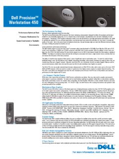
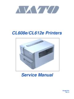
2 16 System Expansion Slots 16 System Level Environmental and Operating Conditions 17 Power 18-19 Audio 20 Communications 20-25 Graphics/Video Controller 26-27 Hard Drives 28-30 Optical Drive 31-32 Media Card Reader 33 BIOS Defaults 34 Chassis Enclosure and Ventilation Requirements 35 Acoustic Noise Emission Information 36-38 dell optiplex 3010 TECHNICAL GUIDEBOOK FINAL 3 MINI TOWER COMPUTER (MT) VIEW 2 3 4 5 6 7 8 9 1 10 11 12 13 14 15 16 FRONT VIEW 1 Power Button, Power Light 6 Optical Drive (optional) 2 Optical Drive Bay (optional) 7 Optical Drive Eject Button 3 Microphone Connector 8 USB Connectors (2) 4 Headphone Connector 9 Drive Activity Light 5 Diagnostic Lights (4) BACK VIEW 10 Power Supply Diagnostic Light 14 Expansion Card Slots(4)
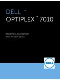
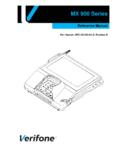
3 11 Power Supply Diagnostic Button 15 Security Cable Slot 12 Power Connectors 16 Padlock Ring 13 Back Panel Connectors 1 2 3 4 5 6 7 8 9 BACK PANEL CONNECTORS 1 Link Integrity Light 6 VGA Connector 2 Network Connector 7 Line-in Connector 3 Network Activity Light 8 Line-out Connector 4 USB Connectors (6) 9 Microphone Connector 5 HDMI Connector dell optiplex 3010 TECHNICAL GUIDEBOOK FINAL 4 Number Name Number Name 1 Front IO connector (FRONTPANEL)) 14 PCI-e 16x Connector (SLOT1) 2 Internal Speaker Connector (INT_SPKR) 15 System fan Connector (FAN_SYS2) 3 System fan Connector (FAN_SYS1) 16 P2 Power Connector(ATX12V) 4 SATA 1 Connector(SATA1) 17 CPU Socket Connector (U27 CPU) 5 SATA 0 Connector(SATA0) 18 CPU fan Connector (FAN_CPU) 6 SATA 2 Connector(SATA2) 19 Memory Connector(DIMM1) 7 SATA 3 Connector(SATA3) 20 P1 power Connector (ATX) 8 Internal USB Connector (USBF1) 21 Power Switch Connector (PWRSW1) 9 Internal USB Connector (USBF1) 22 Memory Connector(DIMM2)
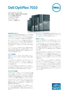
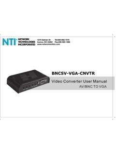
4 10 Internal Audio Connector (AUDIOF1) 23 Battery Connector (BT1) 11 PCI-e 1x Connector (SLOT4) 24 Intrusion Switch Connector (Intruder) 12 PCI-e 1x Connector (SLOT3) 25 KB/MS COM Connector (KBMSCOM1) 13 PCI-e 1x Connector (SLOT2) MT System Board Components dell optiplex 3010 TECHNICAL GUIDEBOOK FINAL 5 DESKTOP COMPUTER (DT) VIEW FRONT VIEW 1 Optical Drive 5 Microphone Connector 2 Optical Drive Eject Button 6 Headphone Connector 3 Power Button, Power Light 7 Drive Activity Light 4 USB Connectors (2) 8 Diagnostic Lights (4) BACK VIEW 9 Padlock Ring 13 Expansion Card Slots(4) 10 Security Cable Slot 14 Power Supply Diagnostic Light 11 Power Connectors 15 Power Supply Diagnostic Button 12 Back Panel Connectors BACK PANEL CONNECTORS 1 Link Integrity Light 6 VGA Connector 2 Network Connector 7 Line-in Connector 3 Network Activity Light 8 Line-out Connector 4 USB Connectors (6)
5 9 Microphone Connector 5 HDMI Connector 1 2 3 4 5 6 7 8 9 10 11 12 13 14 15 1 2 3 4 5 6 7 8 9 dell optiplex 3010 TECHNICAL GUIDEBOOK FINAL 6 DT System Board Components Number Name Number Name 1 Front IO connector (FRONTPANEL)) 14 PCI-e 16x Connector (SLOT1) 2 Internal Speaker Connector (INT_SPKR) 15 System fan Connector (FAN_SYS2) 3 System fan Connector (FAN_SYS1) 16 P2 Power Connector(ATX12V) 4 SATA 1 Connector(SATA1) 17 CPU Socket Connector (U27 CPU) 5 SATA 0 Connector(SATA0) 18 CPU fan Connector (FAN_CPU) 6 SATA 2 Connector(SATA2) 19 Memory Connector(DIMM1) 7 SATA 3 Connector(SATA3) 20 P1 power Connector (ATX) 8 Internal USB Connector (USBF1) 21 Power Switch Connector (PWRSW1) 9 Internal USB Connector (USBF1) 22 Memory Connector(DIMM2) 10 Internal Audio Connector (AUDIOF1) 23 Battery Connector (BT1) 11 PCI-e 1x Connector (SLOT4) 24 Intrusion Switch Connector (Intruder) 12 PCI-e 1x Connector (SLOT3) 25 KB/MS COM Connector (KBMSCOM1) 13 PCI-e 1x Connector (SLOT2)
6 dell optiplex 3010 TECHNICAL GUIDEBOOK FINAL 7 SMALL FORM FACTOR COMPUTER (SFF) VIEW FRONT VIEW 1 Optical Drive 5 Microphone Connector 2 Optical Drive Eject Button 6 Headphone Connector 3 Power Button, Power Light 7 Diagnostic Lights (4) 4 USB Connectors (2) 8 Drive Activity Light BACK VIEW 9 Padlock Ring 13 Power Supply Diagnostic Light 10 Security Cable Slot 14 Back Panel Connectors 11 Power Connectors 15 Expansion Card Slots(2) 12 Power Supply Diagnostic Button BACK PANEL CONNECTORS 1 HDMI Connector 5 Link Integrity Light 2 VGA Connector 6 Network Connector 3 USB Connectors (6) 7 Network Activity Light 4 Line-in/Microphone Connector 8 Line-out Connector 1 2 3 4 5 6 7 8 9 10 11 14 15 12 13 5 6 7 3 1 8 2 4 dell optiplex 3010 TECHNICAL GUIDEBOOK FINAL 8 Number Name Number Name 1 P1 power Connector (ATX) 12 KB/MS COM Connector (KBMSCOM1) 2 System fan Connector (FAN_SYS) 13 Battery Connector (BT1)
7 3 Internal Speaker Connector (INT_SPKR) 14 P2 Power Connector(ATX12V) 4 Front IO connector (FRONTPANEL) 15 CPU Socket Connector (U27 CPU) 5 Internal USB Connector (USBF1) 16 CPU fan Connector (FAN_CPU) 6 PCI-e 16x Connector (SLOT1) 17 Memory Connector(DIMM1) 7 PCI-e 1x Connector (SLOT2) 18 Memory Connector(DIMM2) 8 Internal Audio Connector (AUDIOF1) 19 Power Switch Connector (PWRSW1) 9 SATA 0 Connector(SATA0) 10 SATA 1 Connector (SATA1) 11 Intrusion Switch Connector (Intruder) SFF System Board Components dell optiplex 3010 TECHNICAL GUIDEBOOK FINAL 9 MARKETING SYSTEM CONFIGURATIONS NOTE: Offerings may vary by country.
8 For more information regarding the configuration of your computer, click Start>Help and Support and select the option to view information about your computer. OPERATING SYSTEM MT DT SFF Windows 7 operating system Microsoft Windows 7 Home Basic SP1 (32 and 64 bit), Microsoft Windows 7 Home Premium SP1 (32 and 64 bit), Microsoft Windows 7 Professional SP1 (32 and 64 bit), Microsoft Windows 7 Ultimate SP1 (32 and 64 bit), Other Ubuntu Linux (32bit) OS Media Support Optional CHIPSET MT DT SFF Chipset Intel H61 Express Chipset Non-volatile memory on chipset BIOS Configuration SPI (Serial Peripheral Interface) 64 Mbit (8MB)
9 Located at SPI_FLASH on chipset NIC EEPROM LOM configuration contained within SPI_FLASH no dedicated LOM EEPROM dell optiplex 3010 TECHNICAL GUIDEBOOK FINAL 10 PROCESSOR NOTE: Global Standard Products (GSP) are a subset of dell s relationship products that are managed for availability and synchro-nized transitions on a worldwide basis. They ensure the same platform is available for purchase globally. This allows customers to reduce the number of configurations managed on a worldwide basis, thereby reducing their costs.
10 They also enable companies to implement global IT standards by locking in specific product configurations worldwide. The following GSP processors identi-fied below will be made available to dell customers. NOTE: Processor numbers are not a measure of performance. Processor availability subject to change and may vary by region/country. MT DT SFF Intel Quad Core i5 Processors Intel Core i5-3450 / , 6M, VT-x, 77W X X X Intel Dual Core i3 Processors Intel Core i3-2130 / , 3M, VT-x, 65W X X X Intel Core i3-2120 / , 3M, VT-x, 65W X X X Intel Core i3-2125 / , 3M, VT-x, 65W X X X Intel Pentium Dual Core Processors Intel P