Transcription of DENISON HYDRAULICS Jupiter 900 Driver Card …
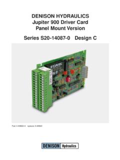
1 Publ. 9-AM683-A replaces 9-AM683 DENISON HYDRAULICSJ upiter 900 Driver CardPanel Mount VersionSeries S20-14087-0 design CMANUFACTURER S NAMEDENISON HYDRAULICSMANUFACTURER S ADDRESS14249 Industrial ParkwayMarysville, Ohio 43040-9504, USAdeclares that the productPRODUCT NAMEJ upiter 900 Driver card (Panel Mount Version)PRODUCT PART NUMBERS20-14087-0conforms to the followingEMC:EN50081-2: March 1994 generic emissions for heavy industry1product specificationsEN55011: 7/1992 radiated or conducted EMI 30-1000 MHzEN50082-2: 1995 generic immunity for heavy industry1 ENV50140: 8/1993 10V/m, 80-1000 MHz Performance Criteria BEN61000-4-2, IEC801-2 electrostatic discharge (ESD)8KV air discharge Performance Criteria A4KV contact discharge Performance Criteria AEN61000-4-4: 5/1995 fast transient rejection2KV power supply wires Performance Criteria BSUPPLEMENTARYINFORMATIONThis product is the panel-mounted version of the Jupiter 900 Driver , S20-14078, whichwas tested in an EMC TEST Laboratory in Germany.
2 The S20-14087 uses the sameelectronic assembly as the S20-14078 less the Euro-style front panel assembly. Henceby construction, this unit complies with the EMC Directive 89/336 and the CE product group was tested in a typical system configuration with DENISONHYDRAULICS Jupiter Series products or recommended second source tested product was mounted in a NEMA 4 enclosure (or equivalent) and all cablesexiting the enclosure were shielded (screened). Enclosure and cable shields were con-nected to earth ground (PE).USA CONTACTO ffice of Director of QualityDENISON HYDRAULICS14249 Industrial ParkwayMarysville, Ohio 43040 EUROPEAN CONTACTDENISON HYDRAULICS Sales Officeor Office of Quality ManagerDENISON HYDRAULICS GmbHGerresheimer Strasse 9D-40721 HildenDeutschlandSee Installation & Operation Guidelines under OF CONFORMITYPER EMC DIRECTIVE 89/336/EEC AND EN45014iIMPROVEMENTS AND CHANGESWORTH NOTING1.
3 Improved power supply specification 22-29 VDC(min-max): unit will tolerateovervoltage excursions up to 40 old version specified 24-28 VDC, (minimum to maximum). If the input voltageaccidentally exceeded 30 volts, including any AC peaks, the converter would fail per-manently. Mobile applications with battery chargers could exceed the 30 volts; butalso fixed industrial applications with unregulated, 28 VDC power supplies will readilyexceed 35 volts due to AC input tolerance and output load Eliminated the two 1/2 amp Micro-Fuses. The new DC-DC converter has internalshort-circuit protection, eliminating the need for fuses.
4 Total current available from 15 Vdc source is 330mA, that is, onboard and off-board. Unit has Front panel STEP COMMAND is functional in both LOCAL and REMOTE versions only worked in LOCAL mode.(This applies to Eurocard version S20-14078 only).4. Added option to permit isolated power source for E-STOP function. This option isfactory set to operate as previous versions. If isolated power source is desired, movejumper JP4 from position A-B (internal GND) to B-C (isolated GND) and connect theisolated power ground to terminal C24 E-STOP RET. It made sense to provide this isolation option to the E-STOP function since the SOFT-STOP andREV CMD function can be : Terminal C24 on versions prior to REV.
5 C was REV CMD RET. Terminal C22 is now the REV CMD RET and SOFT-STOP RET. (We ran out of terminals).5. Added 400 Hz, as a third choice for pulse-width modulation frequency. The factoryset is 200Hz, JP2 (A-B). For 400Hz set jumper JP2 to B-C and for 120Hz removethe jumper (store the jumper on one of the pins).6. The Ramp time minimum values have increased to and seconds. This shouldbe of little consequence in most application. The ramp function can be shut off The IA and IB LED s illuminate somewhat proportionately to the output is a good troubleshooting UPDATE INFORMATIONiiCONTENTSiiiPAG EEuropean EMC Directive 89/336/EECD eclaration of Conformityiproduct up-date informationiitable of contentsiiitechnical specifications1-2power supply requirements1reference voltages1remote inputs1operating temperature1ramp generator1output driver1feedback inputs1input command disable1emergency stop input1reverse CMD input1soft stop input1 LED indicators2potentiometer
6 Adjustments2test points2mechanical2I/O connector pin assignment2product description3system features3general3functional description4-5output4 PWM frequency4input4ramp generator4controls & indicators4emergency stop option4soft stop option5reverse CMD option5ramp-at-zero option5closed-loop-control5procedures6in stallation & operation guidelines6set-up procedure6installation drawings7-9power supply outline7900 drivercard outline8jumper & switch settings9900 Driver functional block diagram10input signal options diagrams11-12remote voltage & potentiometer11current-loop with interlock12application diagrams13-19open-loop control scheme13closed-loop control scheme13most common application14open-loop speed w/ hp limit15closed-loop speed w/ command forward16closed-loop speed w/ com.
7 Forward & hp lmt17closed-loop speed w/ pi18closed-loop speed w/ pi & hp lmt19 TECHNICAL SPECIFICATIONS1 POWER SUPPLY REQUIREMENTS22-29 VDC @ 1 Amp (nominal)REFERENCE VOLTAGESA vailable to user+15 VDC @ 250 mA (max.) 15 VDC @ 250 mA (max.)+10 VDC @ Amps max. 10 VDC @ Amps INPUTSP otentiometer10K Ohms nominal, 5K Ohms minimumInput voltage range 5 VDC, 10 VDCI nput impedance100K Ohms, 200K OhmsCurrent loop input4-20mA, 20mACurrent loop input impedance249 OhmsAuxiliary voltage input 10 VDCR everse command input+15 - +24 VDCSoft stop input+15 - +24 VDCOPERATING TEMPERATURE RANGE0 -65 CRAMP GENERATORS witchable (DIP switch)On or OffPositive ramp (rising) range ramp (rising) range ramp (falling) range ramp (falling) range DRIVERP ulse width modulation (PWM)
8 Driver with current feedback and short circuit frequency120Hz, no jumper200Hz, JP2 position A-B 400Hz JP2 position B-CI (A,B)minimum0-460mAI (A,B)maximum w /24 Ohm loadI min- 800mAFEEDBACK INPUTSH orsepower limiting command 10 VDCM ajor loop 10 VDCINPUT COMMAND DISABLEGnd to disableEMERGENCY STOP INPUTA pply +15 to 24 VDC for normal operationRemove 24 VDC for emergency jumper JP4 for isolated signal CMD INPUTNo connection for normal +15V to 24 VDC and GND to reverse STOP INPUT JP3 factory set to position B-C, soft stop JP3 to position A-B to enable soft 24 VDC and GND for normal 24 VDC for soft INDICATORSP ower 15 VDC supply operationalIAOutput current to coil AIBO utput current to coil BStopBoth A & B coils disabled, same as emergency ADJUSTMENTS+ RampAdjusts positive ramping time RampAdjusts negative ramping timeIAMinAdjusts coil A minimum currentIBMinAdjusts coil B minimum currentIAMaxAdjusts coil A maximum currentIBMaxAdjusts coil B maximum currentTEST POINTSInInput command ( 10 VDC)RampRamp output ( 10 VDC)
9 OutCoil ouput current scaled to 1mV per 1mACoil A is a positive value, Coil B is a negative valueGndSignal ground referenceMECHANICALD imensions, panel mounted100 x 176 mm ( x in.)Connector32 screw-terminals, 2 piece constructionfor quick kg ( Lbs.)I /O CONNECTORPIN ASSIGNMENTSA2:+10V Ref. @ :Test Point Command InS20-14087A4: 10V Ref. @ :Test Point Ramp First-Stage : 5V CommandC6:Test Point Ramp OutA8: 10V CommandC8:Test Point Current Out Coil A/BA10: 10V AUX CommandC10: Coil A PWM OutputA12: Signal GroundC12: Coil A ReturnA14: Current-Loop InC14: Ramp-at-Zero Open-Collector UnitA16: Current-Loop RetC16: Command InvertedA18: Major-Loop FeedbackC18: Coil B PWM OutputA20: HP Limiting CommandC20: Coil B ReturnA22: Soft-Stop InputC22: Soft-Stop Return / Rev.
10 Comm. : Reverse Command InputC24: E-Stop ReturnA26: Signal GroundC26: Command Disable CMDDIS/A28: E-Stop InputC28: +15V @ 250mA Power OutA30: DC Power InputC30: 15V @ 100mA Power OutA32: Power GroundC32: Power GroundTECHNICAL SPECIFICATIONS2 SYSTEM FEATURES Controls 9A electro hydraulic control for Gold Cup Series and premier series openloop pumps Open or closed loop control (w/options card S20-11716-0) Panel mounting (see S20-14078-0 for eurocard version) Separately adjustable positive and negative ramps ( sec.) Multiple input commands Remote potentiometer (10K CT) 5 VDC and 10