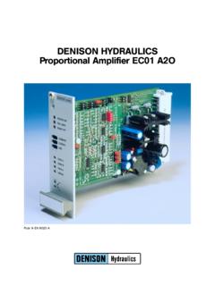
Transcription of DENISONHYDRAULICS …
1 Ordering Code Back to Content DENISON HYDRAULICS. Proportional Amplifier EC01 A1O. Part Nos. 70 00600-8 .. 70 -00603 8 and 70 00605-8. Publ. 9-EN 6010-C, replaces 9-EN 6010-B. CONTENTS. CONTENTS CONTENTS .. 2. MODEL CODE .. 3. REFERENCE TABLE .. 3. DESCRIPTION .. 4. FEATURES .. 4. SPECIFICATION.. 4. 1. SUPPLY VOLTAGE .. 5. 2. REFERENCE VOLTAGES .. 5. 3. COMMAND INPUT .. 6. COMMAND INPUT WITH DIFFERENTIAL INPUT FUNCTION .. 6. COMMAND INPUT WITHOUT DIFFERENTIAL INPUT FUNCTION .. 6. 0 .. + 20 mA Command Signal.. 6. + 4 .. + 20 mA Command Signal .. 6. 0 .. + 5 V Command Signal.. 6. 0 .. + 10 V Command Signal .. 7.
2 Customised Command Signal .. 7. Command Value From An External Potentiometer .. 7. Command Value From An External Signal Source .. 7. 4. DITHER.. 8. DITHER FREQUENCY 250 Hz .. 8. DITHER FREQUENCY 150 Hz.. 8. DITHER AMPLITUDE .. 8. 5. MAXIMUM CURRENT RANGE .. 8. Maximum Current 3000 mA .. 8. Maximum Current 1600 mA .. 8. 6. CONTROL INPUTS.. 9. STOP .. 9. RAMP OFF .. 9. 7. SENSOR INPUTS.. 9. 8. CONTROL OUTPUTS.. 9. 9. JUMPER JP1 JP2 .. 10. COMMAND MEASURING POINT .. 10. JUMPER JP3 .. 10. JUMPER JP4, JP5, JP6, JP7, JP8.. 10. CURRENT MEASURING POINT .. 10. FEEDBACK MEASURING POINT .. 10. 10. TRIMMING POTENTIOMETERS.
3 11. IMIN Setting .. 11. IMIN Step Function .. 11. IMAX Setting .. 11. 11. RAMPS .. 11. 12. TEST AND SET UP INSTRUCTIONS.. 12. 13. LAYOUT DIAGRAM .. 13. 14. STANDARD PIN ASSIGNMENT.. 13. 15. SCHEMATIC DIAGRAM.. 14. 16. CONNECTION DIAGRAM (Example) .. 14. 17. JUMPER AND DIP SWITCH SETTING .. 15. For P2 (VP01 B) & 4VP01 12 V solenoid .. 15. For P2 (VP01 B) 24 V solenoid .. 15. For 4DP02 E, 4DP03 E & 4DP06 E 12 V solenoid .. 16. 18. TROUBLESHOOTING .. 17. 2 Ordering Code Back to Content MODEL CODE, REFERENCE TABLE. MODEL CODE Model Number: EC01 A O. Series A = Analogue version 1 = for valves with 1 solenoid O = Open loop REFERENCE TABLE Factory setting Dither Current Series Sol.
4 Order No. Frequency Amplitude lnom lmin P2 (VP01-B) 12 V 701-00600-8 250 Hz 120 mA 2300 mA 0 mA. 24 V 701-00601-8 150 Hz 35 mA 800 mA 0 mA. 4VP01 12 V 701-00600-8 250 Hz 120 mA 2300 mA 0 mA. 4RP01 12 V 701-00605-8 250 Hz 150 mA 2200 mA 0 mA. 4DP02E 12 V 701-00602-8 150 Hz 300 mA 2950 mA 0 mA. 4DP03E. 12 V 701-00603-8 150 Hz 150 mA 2200 mA 0 mA. 4DP06E. 3 Ordering Code Back to Content DESCRIPTION, FEATURES, SPECIFICATION. DESCRIPTION The proportional amplifier EC01 A1O has been developed to control several DENISON hydraulic proportional valves, which operate with one (1) solenoid. The various requirements of the valves, for example nominal current, dither etc.
5 Can be selected on the proportional amplifier by DIP switch settings. The factory settings are shown on page 15, 16. FEATURES x 24 VDC supply x reverse polarity supply voltage protection x solenoid output short circuit protected x an external signal can start and stop the proportional amplifier (Stop-function). x an external signal can switch the ramp function on and off x linear and, over a wide range, customer adjustable ramp up and ramp down time x dither amplitude adjustable x three different dither frequencies selectable by DIP switch settings x all industry standard command signals can be connected x DIN 41612 connector type F (48 pin B-D-Z).
6 X fulfils all the requirements of EMV and is CE certified SPECIFICATION x Dimensions Euro card format 160 x 100 mm x Front plate dimensions 3U / 8HP ( x mm). x Weight approx. 250 g x Connector DIN 41612, type F, 48 pin x Supply voltage 24 VDC nominal x Voltage range 20 .. 32 VDC (battery or AC voltage, rectified and smoothed, ripple < 5 %). x Current approx. 200 mA (+ solenoid current). x Reference voltages 15 V ( 5 %) 50 mA. 10 V ( %) 10 mA. x Five Inputs Command signal must be positive! 1. Voltage + 5 V. 2. Voltage 0 .. + 10 V. 3. Voltage customised selectable, R83 = 20 k / V. (see layout diagram page 13).
7 4. Current 0 .. + 20 mA. 5. Current + 4 .. + 20 mA. x Output voltage 24 V PWM for the solenoid x Output current l MAX approx. 2700 mA. x Range of adjustments: l MAX A lMIN .. 2700 mA. l MIN A 0 .. approx. 50 % of lMAX. Ramp up 1 .. 50 V/s ( 20 %). Ramp down 1 .. 50 V/s ( 20 %). x Dither amplitude 0 .. 300 mA. x Dither frequency 100 Hz, 150 Hz, 250 Hz (selectable by DIP switch, see layout diagram page 13). x Storage temperature 40 hC .. + 125 hC. x Operating temperature 0 hC .. + 70 hC. 4 Ordering Code Back to Content FUNCTIONAL DESCRIPTION MAIN BOARD. 1. SUPPLY VOLTAGE The proportional amplifier requires an external DC power supply.
8 A diode on the input protects the board against a power supply connected with the wrong polarity. Because the amplifier is a DC/DC converter the current consumption is less than the solenoid current. Several amplifiers can be connected to one power supply, which then has to meet the following requirement: PMAX = n x P1. (P1 = requirement for one board, n = number of boards connected in parallel). The DC voltage must be between 20 and 32 VDC. When the amplifier is used to control a valve with a 24 V solenoid then a voltage supply at the top end of the tolerance band (at least > 26 V) is recommended. This is to ensure that the solenoid has sufficient current at higher temperatures.
9 B/D28 = + VSupply B/D30 = 0 VSupply Z2, Z32 = Earth (necessary for EMV). There is a current compensating coil in the supply line, with the result that the 0 V. line of the supply voltage is not identical with the ground potential of the amplifier. For this reason no connection may be made between the 0 V line of the supply voltage and the analogue ground of the amplifier! 2. REFERENCE VOLTAGES The reference voltages 15 V and 10 V (stabilised) are generated by a switched mode DC/DC converter on the board. B2 = + 15 V unstabilised approx. 50 mA. B4 = 15 V unstabilised approx. 50 mA. D2 = + 10 V stabilised approx.
10 10 mA. D4 = 10 V stabilised approx. 10 mA. The reference voltages are used additionally to power external command potentio- meters, transducers or external electronic components for example 5-channel command card. Furthermore the amplifier has a stabilised 24 VDC supply for transducers, position switches etc. D6, D32 = + 24 V stabilised approx. 80 mA. B6 = GND. 5 Ordering Code Back to Content FUNCTIONAL DESCRIPTION MAIN BOARD. 3. COMMAND INPUT Five different current and voltage signals can be connected to the proportional amplifier. This accommodates all the industry standard input signals. The com- mand input is set up as a differential input.
