Transcription of DENISON HYDRAULICS Jupiter 900 Driver Card Panel …
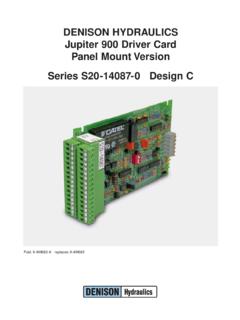
1 Publ. 9-AM683-A replaces 9-AM683 DENISON HYDRAULICSJ upiter 900 Driver CardPanel Mount VersionSeries S20-14087-0 Design CMANUFACTURER S NAMEDENISON HYDRAULICSMANUFACTURER S ADDRESS14249 Industrial ParkwayMarysville, Ohio 43040-9504, USAdeclares that the productPRODUCT NAMEJ upiter 900 Driver card ( Panel Mount Version)PRODUCT PART NUMBERS20-14087-0conforms to the followingEMC:EN50081-2: March 1994 generic emissions for heavy industry1product specificationsEN55011: 7/1992 radiated or conducted EMI 30-1000 MHzEN50082-2: 1995 generic immunity for heavy industry1 ENV50140: 8/1993 10V/m, 80-1000 MHz Performance Criteria BEN61000-4-2, IEC801-2 electrostatic discharge (ESD)8KV air discharge Performance Criteria A4KV contact discharge Performance Criteria AEN61000-4-4: 5/1995 fast transient rejection2KV power supply wires Performance Criteria BSUPPLEMENTARYINFORMATIONThis product is the Panel -mounted version of the Jupiter 900 Driver , S20-14078, whichwas tested in an EMC TEST Laboratory in Germany.
2 The S20-14087 uses the sameelectronic assembly as the S20-14078 less the Euro-style front Panel assembly. Henceby construction, this unit complies with the EMC Directive 89/336 and the CE product group was tested in a typical system configuration with DENISONHYDRAULICS Jupiter Series products or recommended second source tested product was mounted in a NEMA 4 enclosure (or equivalent) and all cablesexiting the enclosure were shielded (screened). Enclosure and cable shields were con-nected to earth ground (PE).USA CONTACTO ffice of Director of QualityDENISON HYDRAULICS14249 Industrial ParkwayMarysville, Ohio 43040 EUROPEAN CONTACTDENISON HYDRAULICS Sales Officeor Office of Quality ManagerDENISON HYDRAULICS GmbHGerresheimer Strasse 9D-40721 HildenDeutschlandSee Installation & Operation Guidelines under OF CONFORMITYPER EMC DIRECTIVE 89/336/EEC AND EN45014iIMPROVEMENTS AND CHANGESWORTH NOTING1.
3 Improved power supply specification 22-29 VDC(min-max): unit will tolerateovervoltage excursions up to 40 old version specified 24-28 VDC, (minimum to maximum). If the input voltageaccidentally exceeded 30 volts, including any AC peaks, the converter would fail per-manently. Mobile applications with battery chargers could exceed the 30 volts; butalso fixed industrial applications with unregulated, 28 VDC power supplies will readilyexceed 35 volts due to AC input tolerance and output load Eliminated the two 1/2 amp Micro-Fuses.
4 The new DC-DC converter has internalshort-circuit protection, eliminating the need for fuses. Total current available from 15 Vdc source is 330mA, that is, onboard and off-board. Unit has Front Panel STEP COMMAND is functional in both LOCAL and REMOTE versions only worked in LOCAL mode.(This applies to Eurocard version S20-14078 only).4. Added option to permit isolated power source for E-STOP function. This option isfactory set to operate as previous versions. If isolated power source is desired, movejumper JP4 from position A-B (internal GND) to B-C (isolated GND) and connect theisolated power ground to terminal C24 E-STOP RET.
5 It made sense to provide this isolation option to the E-STOP function since the SOFT-STOP andREV CMD function can be : Terminal C24 on versions prior to REV. C was REV CMD RET. Terminal C22 is now the REV CMD RET and SOFT-STOP RET. (We ran out of terminals).5. Added 400 Hz, as a third choice for pulse-width modulation frequency. The factoryset is 200Hz, JP2 (A-B). For 400Hz set jumper JP2 to B-C and for 120Hz removethe jumper (store the jumper on one of the pins).6. The Ramp time minimum values have increased to and seconds.
6 This shouldbe of little consequence in most application. The ramp function can be shut off The IA and IB LED s illuminate somewhat proportionately to the output is a good troubleshooting UPDATE INFORMATIONiiCONTENTSiiiPAG EEuropean EMC Directive 89/336/EECD eclaration of Conformityiproduct up-date informationiitable of contentsiiitechnical specifications1-2power supply requirements1reference voltages1remote inputs1operating temperature1ramp generator1output driver1feedback inputs1input command disable1emergency stop input1reverse CMD input1soft stop input1 LED
7 Indicators2potentiometer adjustments2test points2mechanical2I/O connector pin assignment2product description3system features3general3functional description4-5output4 PWM frequency4input4ramp generator4controls & indicators4emergency stop option4soft stop option5reverse CMD option5ramp-at-zero option5closed-loop-control5procedures6in stallation & operation guidelines6set-up procedure6installation drawings7-9power supply outline7900 drivercard outline8jumper & switch settings9900 Driver functional block diagram10input signal options diagrams11-12remote voltage & potentiometer11current-loop with interlock12application diagrams13-19open-loop control scheme13closed-loop control scheme13most common application14open-loop speed w/ hp limit15closed-loop speed w/ command forward16closed-loop speed w/ com.
8 Forward & hp lmt17closed-loop speed w/ pi18closed-loop speed w/ pi & hp lmt19 TECHNICAL SPECIFICATIONS1 POWER SUPPLY REQUIREMENTS22-29 VDC @ 1 Amp (nominal)REFERENCE VOLTAGESA vailable to user+15 VDC @ 250 mA (max.) 15 VDC @ 250 mA (max.)+10 VDC @ Amps max. 10 VDC @ Amps INPUTSP otentiometer10K Ohms nominal, 5K Ohms minimumInput voltage range 5 VDC, 10 VDCI nput impedance100K Ohms, 200K OhmsCurrent loop input4-20mA, 20mACurrent loop input impedance249 OhmsAuxiliary voltage input 10 VDCR everse command input+15 - +24 VDCSoft stop input+15 - +24 VDCOPERATING TEMPERATURE RANGE0 -65 CRAMP GENERATORS witchable (DIP switch)On or OffPositive ramp (rising) range ramp (rising) range ramp (falling) range ramp (falling) range DRIVERP ulse width modulation (PWM)
9 Driver with current feedback and short circuit frequency120Hz, no jumper200Hz, JP2 position A-B 400Hz JP2 position B-CI (A,B)minimum0-460mAI (A,B)maximum w /24 Ohm loadI min- 800mAFEEDBACK INPUTSH orsepower limiting command 10 VDCM ajor loop 10 VDCINPUT COMMAND DISABLEGnd to disableEMERGENCY STOP INPUTA pply +15 to 24 VDC for normal operationRemove 24 VDC for emergency jumper JP4 for isolated signal CMD INPUTNo connection for normal +15V to 24 VDC and GND to reverse STOP INPUT JP3 factory set to position B-C, soft stop JP3 to position A-B to enable soft 24 VDC and GND for normal 24 VDC for soft INDICATORSP ower 15 VDC supply operationalIAOutput current to coil AIBO utput current to coil BStopBoth A & B coils disabled, same as emergency ADJUSTMENTS+ RampAdjusts positive ramping time RampAdjusts negative ramping timeIAMinAdjusts coil A minimum currentIBMinAdjusts coil B minimum currentIAMaxAdjusts coil A maximum currentIBMaxAdjusts coil B maximum currentTEST POINTSInInput command ( 10 VDC)RampRamp output ( 10 VDC)
10 OutCoil ouput current scaled to 1mV per 1mACoil A is a positive value, Coil B is a negative valueGndSignal ground referenceMECHANICALD imensions, Panel mounted100 x 176 mm ( x in.)Connector32 screw-terminals, 2 piece constructionfor quick kg ( Lbs.)I /O CONNECTORPIN ASSIGNMENTSA2:+10V Ref. @ :Test Point Command InS20-14087A4: 10V Ref. @ :Test Point Ramp First-Stage : 5V CommandC6:Test Point Ramp OutA8: 10V CommandC8:Test Point Current Out Coil A/BA10: 10V AUX CommandC10: Coil A PWM OutputA12: Signal GroundC12: Coil A ReturnA14: Current-Loop InC14: Ramp-at-Zero Open-Collector UnitA16: Current-Loop RetC16: Command InvertedA18: Major-Loop FeedbackC18: Coil B PWM OutputA20: HP Limiting CommandC20: Coil B ReturnA22: Soft-Stop InputC22: Soft-Stop Return / Rev.