Transcription of Density Error and its Correction in Boiler Drum Level ...
1 Density Error and its Correctionin Boiler Drum Level IndicationINTRODUCTIONB oiler steam drum water Level is one ofthe most important power plant para-meters to measure and control. If thelevel is too low, Boiler tubes will bedamaged by overheating. If the Level istoo high, the superheater tubes andthe turbine may be damaged by mois-ture or water treatment chemical car-ryover. As Boiler operating pressuresand Boiler drum wall thickness haveincreased, many boilers have becomesmaller. This reduced Boiler drum vol-ume demands even more accuratelevel variety of instruments are availableand approved by the ASME for powerboiler Level indication. However, simplyspecifying one or more of these instru-ments will not guarantee that the boil-er Level will be indicated user must thoroughly understandthe operating principles of each instru-ment, instrument installation require-ments and the Boiler difference in the water densitybetween the Level instrument and theboiler is the major source of Level purpose of this evaluation was to 1996 Yarway CorporationPresented at the InternationalSociety for Measurement andControl (ISA) Conference,October, 1995 ABSTRACTThe requirements for power Boiler Level indication are clearly stated in the ASME Boiler and Pressure Code SectionI, Paragraph In addition to the direct reading gage glass, remote liquid Level indicators of various types arepermitted under certain design of the instrument selected, consideration must be given to the Level Error caused by connecting anexternal device to the Boiler drum.
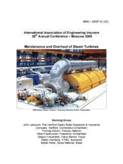
2 The Error is inherent because the Level measuring instrument is at a lower tem-perature than the mechanical and electronic solutions are available to minimize the Level indication Error . The purpose ofthis evaluation was to determine the actual Level Error under various laboratory conditions for three types of waterlevel gages and for an electronic Level gage column. Lab measurements were compared with both design theoryand field observations. All this information was then used together to improve product design, application andinstallation procedures that would minimize Boiler Level indication the actual Level Error of sev-eral instruments under various con-trolled laboratory conditions. Thesemeasurements would then be com-pared with both design theory andfield observations to develop installa-tion requirements and an understand-ing of specific application INDICATIONREQUIREMENTSThe requirements for Boiler Level indi-cation are clearly stated in the ASMEB oiler and Pressure Vessel Code,Section I, Paragraph A combi-nation of gage glasses and remotelevel indicators are required as follows:Each Boiler (except forced flowsteam generators with no fixed steamand waterline, and high temperaturewater boilers of the forced circulationtype that have no steam and waterline)shall have at least one water gageglass.
3 (Figure 1a).Boilers operated at pressures over400 psi (except electric boilers of theelectrode type) shall have two watergage glasses (Figure 1b).Boilers with safety valves set at orabove 400 psi may operate two inde-pendent remote Level indicatorsinstead of one of the two requiredgage glasses (Figure 1c). When bothremote Level indicators are in reliableoperation, the remaining gage glassmay be shut off, but shall be main-tained in serviceable condition. (CodeCase 2109)REMOTE LEVELINDICATORS Several devices have been developedover the years to take advantage ofthe option offered by the Boiler Codefor two independent remote Level indi-cators instead of one of the tworequired gage glasses. These Pressure are available in both themechanical and electronic type(Figure 2). Both measure the differ-ential pressure between a refer-ence water Level and the Water Level Gage(Figure 3).
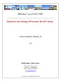
4 This device measureswater Level through conductivityprobes installed in a water columnconnected to the Level ERRORW ater Level gages and all types ofremote Level indicators are affected bydensity Level Error . This Level measure-ment Error occurs because the watermeasured by the device is colder thanthe Boiler water, creating a Density dif-ference. This system can be explainedand modeled by a U Tube Manometer(Figure 4).The manometer contains fluid withthree different densities. On one side issaturated water with Boiler water den-sity Dd. On the other side are two flu-ids: water in the gage with anunknown Density Dg, and saturatedSteam with Density pressure balance at point A in thissystem produces the following rela-tionships:Equation HgDg+ HsDsEquation Hd- HgEquation (Dd- Ds)Dg- DsEquation (Dg- Ds)Dd- DsThe use of these formulas to deter-mine the actual drum water Level , Hd,can be explained with the : Boiler operating pressure 3000 gage temperature is 20 Fbelow saturated steam , water Level in the gage is 20 inch-es above the water the steam tables.
5 Ds= lbm/ft3Dd= lbm/ft3(Assume theaverage water temperaturein the drum is 10 F belowsaturation)Dg= lbm/ft3Hd= 20 inches( - ) - inches, or a 10% factors that determine the magni-tude of the Level Error are the operatingFigure 1 ASME Boiler AND PRESSURE VESSELCODE REQUIREMENTS2 REMOTE Level INDICATOR DIFFERENTIAL PRESSUREF igure 2 ELECTRONIC WATER Level GAGEF igure 3 MechanicalElectronic3 Level GAGE AND U TUBE EQUIVALENTF igure 4 GAGE OPERATING PRESSURE AND SUBCOOLING EFFECT ON Level ERRORF igure 5 HdDd= HgDg+ HsDs4 Level GAGE WATER FLOW DYNAMICSF igure 6pressure, the gage subcooling, andthe Boiler drum Level above the gagereturn connection. Figure 5 shows theeffect of operating pressure and gagesubcooling on gage Error . As pressureincreases, the Density of saturated liq-uid and saturated steam converge(Figure 5a). As gage subcoolingincreases, the Level Error increases(Figure 5b). As the drum Level Hdincreases, the Level Error increasesproportionally.
6 Hdcan be minimized byreturning the water pipe from the gagehorizontlly to the drum, and by design-ing the drum water connection to be aminimum distance below the lowestgage view , a significant questionremains unanswered. What is theaverage gage temperature and corre-sponding Density Dg? Level GAGE DYNAMICSS tandard Level gages and electroniclevel gages connected to the Boiler arenot in a static condition. If they were,the water temperature in the gagewould be near ambient. Referring toFigure 6, steam condenses in the sup-ply piping and upper gage to the gagewaterline. This saturated water raisesthe gage water Level slightly above theequilibrium point. The excess waterflows back into the Boiler drum. Thecirculation flow depends upon thecondensing steam rate and the vol-ume in the gage and water return condensing steam enters thegage at the saturation condensate continues to cooluntil it re-enters the Boiler .
7 A profile ofthis temperature gradient is shown inFigure Level gages are connected tothe Boiler with a tie bar or water col-umn because the visibility of the gagemay be adversely affected by exces-sive water flowing over the glass. Thetie bar short circuits the excess waterfrom the steam supply piping. Theonly flow through the gage is fromsteam condensing in the gage itselfand the gage and remote Level indicationdevices will indicate incorrectly if boilerpressure decreases suddenly. Thetemperature of the water in the gageor reference column is normally withina hundred degrees of the saturationtemperature. If the Boiler pressureshould decrease rapidly, the water inthe gage will flash to steam. Thesteam bubbles will cause the Level inGAGE WATER TEMPERATURE PROFILEthe glass to rise and will often obliter-ate the meniscus. Indication will returnto normal when thermal equilibrium isre-established.
8 Systems utilizing a ref-erence column will indicate high aswater in the reference leg flashes tosteam. Indication will return to normalvery slowly as steam condenses torefill the reference leg. The referenceleg can also be manually filled toestablish proper indication morequickly. GAGE CORRECTIONOPTIONSE very Level measurement device mustbe corrected in some manner to com-pensate for Density Level Error . A num-ber of techniques have evolved overthe years to address each Pressure Indicator,mechanical type(Figure 2).Thedevice is installed with a tempera-ture compensated reference col-umn. The purpose of this equip-ment is to heat the water in the ref-erence leg to a value that is halfwaybetween saturation and corrects the indication if thelevel is at the mid scale position,regardless of pressure. An addi-tional pressure sensing device isadded to correct the pointer forwater levels that are above orbelow the mid scale Pressure Indicator, elec-tronic type(Figure 2).
9 The mostsophisticated of the devices mea-sures the differential pressure ofthe reference and variable legs withboth at ambient temperature. Theambient temperature and the boil-er operating pressure are alsomeasured. An analog or digital pro-gram then corrects the apparentdifferential for Boiler water densityto indicate the Boiler sophisticated devices are cal-ibrated to read correctly at onlyone pressure, usually the normaloperating pressure. They will indi-cate improperly when operated atpressures above or below the cali-bration Level Gages, direct readingand electronic discussedearlier, the primary difficulty in cal-culating the Level Error for devicesof this type is to determine theaverage gage water temperatureand corresponding water this is calculated or mea-sured, then the gage glass is phys-ically installed in a lower position tocompensate for this Error . Steamheated Level gages are availablethat significantly reduce the densityerror.
10 But these may be especiallysusceptible to Boiler pressure tran-sients. The electronic gage can becorrected by locating each probeindividually to correct for the errorat that Level ERRORTEST PROGRAM ANDTEST RESULTSA test apparatus was constructed inthe Yarway Test Lab, shown in Figure7, to measure the Level Error and gagetemperature of various gages under avariety of conditions. Probes of thesame type used in the electronic gagewere installed with 1/2" spacing in areference Level column. The water inthe reference column was maintainedwithin 10 F of saturation Level was maintained at a knownpoint by throttling control valve V1. Thegage under test was connected to thereference column with typical pipingand on various devices were per-formed with a variety of connectingpipe sizes, pipe lengths, operatingpressures and insulation most of this information is pro-prietary in nature, only general charac-teristics will be 8 shows the Level Error andtemperature gradient for a typicalgage as a function of operating pres-sure.