Transcription of DESCRIPTION SPECIFICATIONS - Iota Engineering
1 LEDP roduct SPECIFICATIONS are subject to change without noticeILB-CP12-A: x x (mounting center )MOUNTING CENTER : x x (mounting center )PRODUCT specification SHEETMODEL NO: TYPE: PROJECT: COMMENTS: SPECIFICATIONS IOTA Engineering PO BOX 11846 TUCSON, AZ 85734 TEL: 1-800-866-IOTA (4682) FAX: (520) 741-2837 WEB: REV 081318 FEATURES Input Voltage ..(Universal) 120-277 VAC, 50/60 HzInput Rating (120V/277V).. Watts (max) Output Voltage1.
2 10-60 VDC Class 2 CompliantOutput Current .. (@10 VDC) - (@60 VDC)Output Power ..12 Watts (constant)Max. AC Driver Output Current .. 3 AdcPower Factor .. Operation .. 90 minutesOperating Temp .. 0 to 55 CTHD .. < 20%Battery ..High Temp Nickel-Cadmium 24 Hour Recharge 7-10 Year Life ExpectancyWeight .. (-A, -R) lbs. (-B, -TM) lbs.
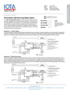
3 (-J, -R-J) .. UL Listed and Classified for factory and field installationPRODUCT ADVANTAGES The ILB-CP12 from IOTA Engineering is a UL Listed and Classified LED emergency driver that allows the same LED fixture to be used for both normal and emergency op-eration.
4 In the event of a power failure, the ILB-CP12 switches to the emergency mode and operates the existing fixture for 90 minutes. The unit contains a battery, charger, and converter circuit in a single can and is available in different mounting configurations for individual fixture requirements. The ILB-CP12 will operate an LED array load at 12 watts with constant power at a rated output voltage of 10V-60V. The Constant Power design of the ILB-CP12 maintains the output wattage to the LED array even as the system voltage OPERATION:12W LED Load @ 10-60 VDC 924 Listed, UL Listed and Classified to FTBVUL 1310 Certified, Output Class 2 Compliant Six mounting configurations available Long life high temperature recyclable Ni-Cad batteryGalvanized steel caseIncludes single-piece TBTS test switch and charge indicator accessory kitFor use with switched or unswitched fixtures5-Year Warranty.
5 See Warranty Page for or exceeds all NEC, IBC, and Life Safety Code Emergency Lighting RequirementsRated for use in Plenum, Damp Location, Recessed Type IC, and Enclosed and Gasketed LuminairesRoHS CompliantUL Listed for factory and field installationConstant Power Design maintains illumina-tion throughout the 90-minute runtime with no light degradationTwo-wire universal AC inputSelf-sensing output voltage allows the CP Series to operate various product types, such as downlights, troffers, or strips, reducing product SKUs for emergency :12 Watts (Constant)MOUNTING CENTER POWER LED EMERGENCY DRIVERDESCRIPTIONP atented.
6 See for output voltage in emergency mode is VDC with a + tolerance of volts IOTA Engineering PO BOX 11846 TUCSON, AZ 85734 TEL: 1-800-866-IOTA (4682) FAX: (520) 741-2837 WEB: REV 081318 ILB-CP12 CONSTANT POWER LED EMERGENCY DRIVERS upply and install IOTA [Insert 12W model number] Constant Power emergency LED driver system as indicated on the plans. The emergency driver shall be designed for [Select Internal or External ] mounting to the luminaire including a self-contained, high-temperature, sealed, maintenance-free nickel cadmium battery rated for a 10-year service life.
7 The unit shall be provided complete with an illuminated push to test switch. The emergency driver system shall be UL class 2 certified in accordance with UL 1310 and shall be UL listed for use in damp locations and in enclosed and gasketed fixtures with a temperature range of 0 to 55 AC input shall be a two-wire, universal voltage capable 120 thru 277 VAC, 50/60 Hz and be UL Listed to Category Control Number (CCN) FTBR, Emergency Light-ing and Power Equipment, and FTBV, Emergency Light-Emitting-Diode Drivers for field installation.
8 Maximum input power of the emergency driver shall be unit charger shall consist of a two-stage charging system which samples the battery in relation to its temperature, state of charge and input voltage fluctuations. The charger shall be current limited, temperature compensated, short-circuit protected with reverse polarity protection. A low voltage battery disconnect (LVD) circuit shall be provided and will disconnect the load and circuitry from the battery when it reaches approximately 80 to 85% of its nominal terminal voltage, preventing a non-recoverable, deep-discharge condition as well as equipment initialization failure when utility power is restored.
9 The unit shall achieve a full recharge in emergency driver shall accommodate an LED load with a forward voltage requirement ranging from 10 to 60 VDC. The output voltage sensing shall be automatic and instantaneous with a resulting, inversely-proportional current to maintain constant power to the LED array with an output tolerance of +/- 3%. The unit shall supply the rated load for a minimum of 1 1/2 hours or to 87 1/2% of rated battery terminal voltage. The output power to the LED load during emergency operation shall be held constant 12 watts from minute one throughout the entire emergency run time resulting in no loss or degradation of the light source during emergency operation.
10 The unit shall be furnished with an electronic, AC-lockout circuit which will connect the battery when the AC circuit is activated, and an electronic brownout circuit which will enable a transfer to emergency operation when utility power dips below an acceptable level. Maximum remote mounting distance of the emergency driver shall be See for CONDUIT TOTEST ACCESSORIES (36 )WIRING TOFIXTUREWIRING TO FIXTURE ANDTEST ACCESSORIESFLEXIBLE CONDUIT TOFIXTURE (36 )FLEXIBLE CONDUIT TOTEST ACCESSORIES (36 )FLEXIBLE CONDUIT WITHTEST ACCESSORY (36 )WIRING TOFIXTUREORDERING GUIDEFLEXIBLE CONDUIT TOFIXTURE (36 )FLEXIBLE CONDUIT TOTEST ACCESSORIES (36 )WIRING TO FIXTURE ANDTEST ACCESSORIESA (Dual Flex)ILB-CP12B (Integral Non-Flex)ILB-CP12-A-ILB-CP12-BJ (Single Flex Junction Mount)