Transcription of Design and Implementation of Astable …
1 IOSR Journal of Electrical and Electronics Engineering (IOSR-JEEE) e-ISSN: 2278-1676,p-ISSN: 2320-3331, Volume 12, Issue 1 Ver. II (Jan. Feb. 2017), PP 22-29 DOI: 22 | Page Design and Implementation of Astable multivibrator using 555 Timer Md. Moyeed Abrar Department of Computer Science &Engineering, Khaja Banda Nawaz College of Engineering, Kalaburagi, Karnataka, India Abstract: The 555 timer is widely used as IC timer circuit and it is the most commonly used general purpose linear integrated circuit.
2 It can run in either one of the two modes: Monostable (one stable state) or Astable (no stable state). In the Monostable mode it can produce accurate time delays from microseconds to hours. In the Astable mode it can produce rectangular waveforms with a variable Duty cycle. The simplicity and ease with which both the multivibrator circuits can be configured around this IC is one of the main reasons for its wide use. The state of the art presented in the paper is the Design and Implementation of an Astable multivibrator using 555 timer IC, generating non-sinusoidal waveform in the form of Rectangular waveform as well as capacitor voltage waveform in the form of ramp waveform.
3 Keywords: Astable multivibrator , Duty cycle, Ramp waveform, Rectangular waveform, 555 timer. I. Introduction Oscillators are broadly classified into two categories namely sinusoidal and non-sinusoidal oscillators. Sinusoidal oscillators produce a sine wave output and the non-sinusoidal oscillators produce a square or pulsed output. A multivibrator circuit is basically a non-sinusoidal oscillator with a regenerative feedback. A multivibrator circuit is a two state circuit that has zero, one or two stable output states.
4 Depending on the number of stable output states there are three basic types of multivibrator circuits namely Bistable multivibrator having two stable states, Monostable multivibrator having one stable state and Astable multivibrator having zero stable states. [1] In the case of Monostable and Bistable multivibrator an external trigger pulse is required for their operation whereas in the case of Astable multivibrator it has automatic built in triggering which switches it continuously between its two unstable states both SET and RESET.
5 There are two main components in every multivibrator namely the bistable circuit and the two passive networks that are connected in a basic feedback loop. The networks in the circuit can be Monostable (resistive), Astable (resistive-capacitive) or bistable. Astable multivibrator is built of two amplifying stages that are connected in a positive feedback loop using two resistive-capacitive coupling networks. The elements used for amplification may be junction field effect transistors, bipolar junction transistors, vacuum tubes, operational amplifiers or any other type of amplifier.
6 They are essentially used in wide variety of systems where a timed interval or a square wave is required [1], [2]. The 555 timer can be connected to run as an Astable multivibrator . When used in this way, the 555 timer has no stable states, which implies that it cannot remain indefinitely in either state. Stated in another way, it oscillates when operated in the Astable mode and produces a Square or Rectangular output signal. The rest of the paper is organized into sections as follows: section II describes the overview of the Astable multivibrator using timer IC 555.
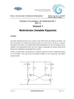
7 Section III focuses on the system Design . Experimental results and discussions are reported in Section IV. Finally section V summarizes the paper and presents the concluding remark. II. Astable multivibrator Using Timer IC 555 Overview The basic 555 timer based Astable multivibrator circuit is depicted in fig 1. Initially, capacitor C is fully discharged, which forces the output to go to the HIGH state. An open discharge transistor allows capacitor C to charge from +Vcc through resistors R1 and R2.
8 When the voltage across C exceeds +2 Vcc /3, the output enters the LOW state and the discharge transistor is switched ON at the same time. Capacitor C starts to discharge through R2 and the discharge transistor inside the IC. When the voltage across C falls below + Vcc /3, the output enters the HIGH state. The charge and discharge cycles repeat and the circuit behaves as a free running multivibrator . Terminal-4 of the IC is the RESET terminal. Usually, it is connected to +Vcc.
9 If the voltage at this terminal is driven below , the output is forced to the LOW state overriding command pulses at terminal-2 of the IC. HIGH state and LOW state time periods are governed by the charge (+ Vcc /3 to +2 Vcc /3) and discharge (+2 Vcc /3 to +Vcc /3) timings. These are given by (1) and (2) respectively. HIGH state time period, THIGH= x (R1+R2) x C (1) LOW state time period, TLOW= x R2 x C (2) Design and Implementation of Astable multivibrator using 555 Timer DOI: 23 | Page Fig.
10 1 Astable multivibrator circuit using 555 timer. The HIGH state time period is also known as Turn ON time (TON) and the LOW state time period is also known as Turn OFF time (TOFF). The relevant waveforms are shown in fig 2. Astable multivibrator waveforms The time period (T) and frequency (f) of the output waveforms are given by (3) and (4) respectively. Time period, T= x (R1+2R2) x C (3) Frequency f= 1 x (R1+2R2) x C (4) III. System Design Hardware Design . Given frequency= 1 KHz and duty cycle= 60% ( ) Time period T= 1/f= TON+TOFF=1 msec (5) Where TON is the time the output is high and TOFF is the time the output is low.