Transcription of Design and Implementation of FFT/IFFT System Using ...
1 ISSN: 2277-3754. ISO 9001:2008 certified international journal of engineering and innovative technology (IJEIT). Volume 3, Issue 6, December 2013. Design and Implementation of FFT/IFFT System Using Embedded Design Techniques Mazin Rejab Khalil 1 ,Aseel Thamer Ibrahem 2. Assistant Professor Foundation of Technical Education/ Technical College/ Mosul Iraq E-mail: 1 2 Results are displayed Using chip scope window and discussed. Abstract The paper proposes a Design of soft core processor Finally conclusions are introduced. System accommodated to perform Fast Fourier Transform and Inverse Fast Fourier Transform ( FFT/IFFT ) of a discrete input II. CONSTRUCTION OF A SOFT CORE PROCESSOR. signal. A DDR SDRAM 64M byte memory is introduced to the System .
2 System to cope with high density storage requirements of high frequency signals. Xilinx Microprocessor Debugger (XMD) is Embedded Design Kit tools (EDTs) [4] are used to develop used to initialize the DDR SDRAM with the C-language program the soft core processor System that implies micro blaze soft that is used to perform the signal transform. The System is core processor [5]. Processor Local Bus (v ) [6] to transfer designed Using ISE tool software and configured on Spartan-3E. data, addresses, and controls signals. 16 K byte block RAM. FPGA Slice. [7] to act as boot memory with instruction local memory bus Keywords DDR SDRAM, Embedded Design techniques, (ILMB) and data local memory bus (DLMB) [8], interrupt Spartan-3E FPGA Slice, and XMD debugger.
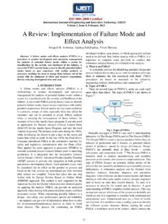
3 Controller, debug module to be connected with chipscope window to display selected captured signals and DDR. I. INTRODUCTION SDRAM connected to PLB via MPMC interface. An embedded System is designed to continuously execute The System requires an I/O port to be used for data a specific set of tasks for a particular application. In general, acquisition therefore 8 bits parallel I/O port is designed and embedded systems have a hardware component and a added to the System Using CIP with the techniques adopted in software component designed to be executed on the hardware. [9]. The hardware component consists of a microprocessor and The hardware part of the designed System with its address associated peripherals.
4 Embedded systems can be utilized in a map is shown in Fig 1. The designed processor System is wide variety of applications, ranging from consumer programmed Using C- language and adapted to calculate the electronics to industrial equipment. FFT/IFFT of a discrete signal. FPGAs serve as a real-time prototyping and Implementation medium on which complete embedded systems can be implemented to test and verify their functionality. This has encouraged embedded systems designers to increasingly use FPGAs as their Implementation medium in order to minimize Design costs and time [1]. In [2], Sheac et al. presented two FFT Implementation approaches, one Implementation as an FPGA co-processor and the other Using only an external digital signal processor.
5 In [3], Mounir Arioua et al. presented an optimized Implementation of the 8- point FFT processor with radix-2. algorithm in R2 MDC architecture. The butterfly- Processing Element (PE) used in the 8-FFT processor reduces the multiplicative complexity by Using a real constant multiplication in one method and eliminates the multiplicative complexity by Using add and shift operations in other proposed method. The paper is organized to include constructing a soft core Processor System Using embedded Design techniques, theoretical review of FFT, IFFT calculation, and developing a (a). C program oriented algorithm for calculating FFT/IFFT . 258. ISSN: 2277-3754. ISO 9001:2008 certified international journal of engineering and innovative technology (IJEIT).
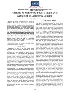
6 Volume 3, Issue 6, December 2013. The first step to perform FFT is to break the transform into the two (N/2)-point transforms and the provides the N-point combining algebra. Each of the (N/2)-point sequences can be decimated further into two sequences of lengths N/4, each (N/4)-point transform is broken into two (N/8)-point DFTs, as shown in Fig 2. This process can be continued until there are log2 N stages it is listed is in the following patterns. (b). Fig 1. The designed embedded processor System (a) . The block diagram of the hardware part (b) . The address map III. FAST FOURIER TRANSFORM. The Fast Fourier Transform is an optimized computational algorithm to implement the Discreet Fourier Transform of an array of N samples.
7 It allows determining the frequency contents of a discreet signal, representing the signal in the frequency domain. The algorithm of Cooley-Tukey is used in this work to perform FFT. The FFT is calculated in two stages, the first stage transforms the original data array into a bit-reverse order array by applying the bit-reversal method, and the second stage processes the FFT in N*log2 (N) operations (by applying Danielson-Lanczos Lemma algorithm) [10] [11]. FFT calculation is based on the DFT equation: ----------------- (1). Where n= 0, 1 N-1 , N: number of samples , x (k): input signal --------------------- (2). is known as twiddle factor. Equation (1) can be broken up in two summations of half the size of the original.
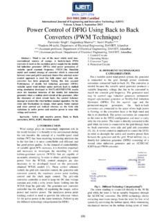
8 The summation is the even terms , E, and the second is the odd terms , O, as shown in equation (3): Fig 2. The flow graph for an eight-point decimation-in- frequency Fast Fourier Transform algorithm ------- (3). E=Even Term O=Odd Term (N/2 Point DFT of even indexed sequence) (N/2point DFT of odd indexed sequence). The flow chart of the prepared program is shown in Fig 3. 259. ISSN: 2277-3754. ISO 9001:2008 certified international journal of engineering and innovative technology (IJEIT). Volume 3, Issue 6, December 2013. 1. Start No m > 2 && j >= m Define PI. Define TWOPI ( *PI). Define SWAP (a,b) Yes j= j-m m= m/2. j= j+m Function of FFT. Void FFT-1 (data [], nn , isign). Data []: array of complex data nn: number of complex samples i= i+2.
9 Isign: if it is set to 1, compute FFT, if it is set to -1, compute IFFT. Yes 3 i < n/2. n= nn* 2 / * complex array is real +imaginary number No Stage one j= 0, i= 0 mmax= 2. Bit reversal method 3. No 5. 2. No j>i n > mmax Stage two Yes End Danielson-Lanzcos Swap the real part Yes SWAP (data [j], data[i]). Swap the complex part SWAP (data [j+1], data[i+1]) istep = 2*mmax;. theta =TWOPI/(isign*mmax);. wtemp = sin( *theta);. wpr = *wtemp*wtemp;. wpi = sin(theta);. No 2 (j/2) < (n/4) wr = ;. wi = ;. Yes Swap the real part SWAP (data [(n-(i+2)], data[(n-(j+2)] m=1. Swap the complex part I. UNITS 6. SWAP (data [((n-(i+2))+1], data[((n-(j+2))+1]). i =m 7. 2. j =i + mmax;. m= n/2 tempr = wr*data[j] - wi*data[j+1].)))))
10 Tempi = wr*data[j+1] + wi*data[j];. data[j] = data[i] - tempr;. data[j+1] = data[i+1] - tempi;. 1 data[i] += tempr;. data[i+1] += tempi;. 4. 260. ISSN: 2277-3754. ISO 9001:2008 certified international journal of engineering and innovative technology (IJEIT). Volume 3, Issue 6, December 2013. 4. i = i + istep 7 Yes i<=n No wr = (wtemp = wr)*wpr - wi*wpi + wr;. wi = wi*wpr + wtemp*wpi + wi;. m = m+ 2 (b). 6 Yes m < mmax No mmax=istep 5. Fig 3. The FFT/IFFT flow chart algorithm IV. RESULTS. An audio signal is introduced to the designed System via the added parallel port to be processed where its FFT and IFFT. are calculated. The audio signal under test is generated in matlab media and transmitted to the designed processor System .