Transcription of DESIGN AND INSTALLATION GUIDE - Gastite
1 SEPTEMBER AND INSTALLATION GUIDEC ommercial I Industrial I ResidentialSECTION 1: INTRODUCTION / SEPTEMBER 2017 Important Lightning Safety Warning 1 PROPERLY BONDING and grounding the Corrugated Stainless Steel Tubing (CSST) system may reduce the risk of damage and fire fr om a lightning strike. Lightning is a highly destructive force. Even a nearby lightning strike that does not strike a structure directly can cause systems in the structure to become electrically energized. Differences in potential between systems may cause the charge to arc between systems. Such arcing can cause damage to CSST, including holes. Bonding and grounding should reduce the risk of arcing and related damage. The building owner should confirm that a qualified contractor has properly bonded the CSST gas system to the grounding electrode system of the premises. Refer to Section Electrical Bonding/Grounding in the Gastite DESIGN & INSTALLATION GUIDE for details on bonding & grounding ALL OWNERS should consult a lightning safety consultant to determine whether INSTALLATION of a light-ning protection system would be required to achieve sufficient protection for all building components fr om lightning.
2 Factors to consider include whether the area is prone to lightning. Areas with high lightning risk in-clude but are not limited to: Alabama, Arkansas, Florida, Georgia, Illinois, Indiana, Iowa, Kentucky, Louisiana, Maryland, Michigan, Mississippi, Missouri, New Mexi-co, North Carolina, Ohio, Oklahoma, Pennsylvania, South Carolina, Tennessee, Texas, Virginia and West Virginia. One currently available source of information regard-ing areas more prone to lighting than others is the flash density map provided by the National Weather Service which can be found at Lightning protection systems are beyond the scope of this manual and INSTALLATION guidelines, but are covered by National Fire Protection Association, NFPA 780, the Standard for the INSTALLATION of Lightning Protection Systems, and other standards. 3 THE OWNER should confirm with the local gas supply utility company that a suitable dielectric union is installed at the service entry of the structure between underground metallic piping and the gas pipes going into the building as required by SAFETY WARNING4 NATIONAL ELECTRIC CODE (NEC), Sec-tion , states that bonding all piping and metal air ducts within the premises will provide additional safety.
3 Gastite recommends that all continuous metallic systems be bonded and grounded. The owner should confirm with an electrical or construction specialist that each continuous metallic system in a structure has been bonded and grounded by an electrical professional in accordance with local building codes. This should include, but is not limited to metallic chimney liners, metallic appliance vents, metallic ducting and piping, electrical cables, and structural DIRECT CONTACT betweencontinous metallic systems and Gastite yellow CSST is prohibited. Maintain as much isolation/separation as reasonably possible when planning and installing gas piping from other continuous metalllic systems. Refer to sec. Routing, in the Gastite D&I GUIDE for INSTALLATION techniques. Consult local building codes as to required separations for CSST fr om such continuous metallic systems including metallic chimney liners, metallic appliance vents, metallic ducting and piping, and insulated or jacketed electrical wiring and cables.
4 See for instance the Indiana Residential Code, section 675 IAC Section ; gas pipe LOCAL BUILDING CODES are controlling, however, as a general practice, fuel gas piping, including CSST, should not be installed within a chase or enclosure that houses a metallic chimney liner or appliance vent that protrudes through the roof. In the event such an INSTALLATION of Gastite yellow CSST is necessary and conforms to local building codes, the metallic chimney liner or vent must be bonded and grounded by a qualified electrical professional, and a separation distance, as specifically permitted by the applicable local building code between the CSST and the metallic chimney liner or vent, is required. Physical contact between CSST and the metallic chimney liner and/or vent is prohibited. If this physical separation cannot be specifically identified in the local building code and achieved or any local building code require-ments cannot be met along the entire length, then rerouting of the CSST is required unless such INSTALLATION is specifically permitted by the local building inspector.
5 2013, Gastite Division, Titeflex CorporationGENERAL 1/20 DIVISION, TITEFLEX CORPORATION / 1116 Vaughn Parkway / Portland, TN / / iiiFLASHSHIELD INSTALLER INFORMATION & UPDATES1) When using the XR3 fitting, proper removal of the outer jacket layer on FlashShield CSST is required for optimal electrical continuity of the system. Using the Jacket Stripping Tool is the easiest way to achieve the correct FlashShield end-prep condition and to ensure electrical continuity of the ) Licensed Installers Only. Every installer of FlashShield or Gastite must first meet all applicable qualifications in accordance with state and/or local requirements as established by the administrative authorities that enforce the plumbing or mechanical codes where gas piping is installed. 3) Qualified Installers Only. In addition to be licensed in the jurisdiction, FlashShield or Gastite corrugated stainless steel tubing (CSST) flexible gas piping material must only be installed by an installer who has been successfully trained through the FlashShield and Gastite training program.
6 4) Check for Updates. Installers should check with their local distributor or at for technical bulletins or updated DESIGN & INSTALLATION Guides for FlashShield or Gastite every ) Proper INSTALLATION . Sound engineering principles and practices must be exercised for the proper DESIGN of fuel gas piping systems, in addition to compliance with local codes. The INSTALLATION instructions and procedures contained in this DESIGN & INSTALLATION GUIDE must be strictly followed in order to provide a safe and effective flexible fuel gas piping system or system modification. All installations must pass inspections by the local official having authority prior to having the gas service turned on. All requirements of the local natural gas utility or propane supplier must also be met. Proper FlashShield End PrepProper XR3 Bushing PlacementGASTITE DIVISION, TITEFLEX CORPORATION / 1116 Vaughn Parkway / Portland, TN / / ivTABLE OF CONTENTS / SEPTEMBER 2017 SECTION GENERAL USER WARNINGS.
7 LIMITATIONS OF THE GUIDELINES .. STANDARDS, LISTINGS AND CODES ..5 SECTION SYSTEM DESCRIPTIONS & SYSTEM DESCRIPTIONS .. G A S T I T E SYSTEM DESCRIPTION .. FLASHSHIELD SYSTEM DESCRIPTION .. COMPONENTS .. CORRUGATED STAINLESS STEEL TUBING ..8 FITTINGS ..10 MANIFOLDS .. MODULAR STUB SYSTEM .. MOUNTING HARDWARE .. PIPE SUPPORT SYSTEM .. STRIKE PROTECTION .. SHUT-OFF VALVES AND QUICK CONNECTS .. Gastite BONDING CLAMPS .. SYSTEM REGULATORS ..16 SECTION SYSTEM I N T RO D U C T I O N .. SYSTEM REQUIREMENTS .. REFERENCE DATA FOR PROPER SYSTEM SIZING .. DETERMINING SYSTEM LAYOUT ..19 ALLOWABLE PRESSURE DROP .. SIZING METHODS ..21 MODIFYING AN EXISTING SYSTEM .. SIZING PROCEDURES AND EXERCISES .. SIZING EXAMPLES .. EXAMPLE 1: SERIES SYSTEM 6"WC ..23 EXAMPLE 2: PARALLEL SYSTEM 6"WC ..25 EXAMPLE 3: PARALLEL SYSTEM 12-14"WC.
8 27 EXAMPLE 4: DUAL PRESSURE SYSTEM 2 PSI TRUNK AND 8"WC APPLIANCE RUNS ..29 EXAMPLE 5: MULTIPLE MANIFOLD SYSTEM .. EXAMPLE 6: SERIES SYSTEM 7"WC - HYBRID .. EXAMPLE 7: PARALLEL SYSTEM 7"WC HYBRID ..34 EXAMPLE 8: SUMMATION METHOD FOR PARALLEL SYSTEM 7"WC HYBRID ..36 EXAMPLE 9: SUMMATION METHOD FOR SERIES SYSTEM 6"WC ..38 EXAMPLE 10: COMMERCIAL ELEVATED PRESSURE SERIES SYSTEM 2 EXAMPLE 11: COMMERCIAL HYBRID SYSTEM 7"WC ..43 45 SECTION INSTALLATION GENERAL PROVISIONS .. FIELD FITTING ASSEMBLY PROCEDURE .. XR3 FITTING TO Gastite YELLOW XR3 FITTING TO FLASHSHIELD CSST ..50 XR3 FITTING TO FLASHSHIELD CSST (WITHOUT STRIPPING TOOL) ..52 OTHER ACCESSORY INSTALLATION .. ROUTING .. VERTICAL RUNS .. HORIZONTAL RUNS .. INSTALLATION CLEARANCE HOLES .. CONCEALED FITTINGS .. MODIFICATIONS TO EXISTING SYSTEMS ..56 Gastite DIVISION, TITEFLEX CORPORATION / 1116 Vaughn Parkway / Portland, TN / / vTABLE OF CONTENTS / SEPTEMBER OUTDOOR.
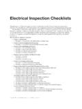
9 FIRE RATED CONSTRUCTIONS .. ROUTING THROUGH MASONRY MATERIAL .. INSTALLATION WITHIN A CHASE .. CLEARANCE FROM THE UNDERSIDE OF A ROOF DECK .. STRIKE PROTECTION .. STRIKE PLATES ..58 STEEL CONDUIT .. METER ..60 APPLIANCE .. MOVEABLE APPLIANCE .. DIRECT CONNECTION NON-MOVEABLE APPLIANCES .. GAS CONVENIENCE OUTLET .. SPECIAL APPLICATIONS ..63 MANIFOLD .. PRESSURE REGULATOR .. INTRODUCTION .. SIZING INSTRUCTIONS ..68 INSTALL ATION .. PERFORMANCE .. REGULATOR OUTLET PRESSURE ADJUSTMENT .. OVER-PRESSURIZATION PROTECTION .. UNDERGROUND INSTALLATIONS .. ELECTRICAL BONDING OF Gastite /FLASHSHIELD CSST ..73 SECTION INSPECTION, REPAIR & MINIMUM INSPECTION REQUIREMENTS .. INSTALLATION CHECKLIST DESCRIPTION .. REPAIR OF DAMAGED CSST .. DETERMINE DAMAGE .. METHOD OF FLASHSHIELD JACKET REPAIR ..76 SECTION PRESSURE/LEAKAGE GENERAL GUIDELINES FOR PRESSURE TESTING.
10 ELEVATED PRESSURE SYSTEMS .. APPLIANCE CONNECTION LEAKAGE CHECK SIZING TABLES & PRESSURE DROP CSST CAPACITY TABLES NATURAL GAS ..79 CSST CAPACITY TABLES NATURAL GAS ELEVATED PRESSURE ..83 CSST CAPACITY TABLES PROPANE GAS ..85 CSST CAPACITY TABLES PROPANE GAS ELEVATED PRESSURE ..87 88 Gastite AND FLASHSHIELD CSST PRESSURE DROP TABLES ..89 IRON PIPE CAPACITY TABLES .. IRON PIPE PRESSURE DROP TABLES .. REFERENCE DATA ..98 SECTION DEFINITIONS ..99 100 SECTION DIMENSIONAL & TECHNICAL REFERENCE DATA .. Gastite SPECIFICATION SHEET .. FLASHSHIELD SPECIFICATION SHEET ..102 103 SECTION WARRANTY ..104 FLEXIBLE GAS PIPING TRAINING PROGRAM TEST ..105 Gastite DIVISION, TITEFLEX CORPORATION / 1116 Vaughn Parkway / Portland, TN / / 2 SECTION 1: INTRODUCTION / SEPTEMBER 2017 SECTION GENERAL USER WARNINGSP lease note that there are specific differences between Gastite and FlashShield throughout this DESIGN and INSTALLATION GUIDE .