Transcription of (Requirements for Electrical Installations – BS 7671 …
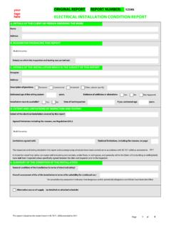
1 DOMESTIC Electrical installation CERTIFICATE (Requirements for Electrical Installations BS 7671 IEE Wiring Regulations)DETAILS OF THE CLEINT ADDRESS OF THE INSTALLATIONC lient andaddress installation address Postcode: Postcode: DETAILS OF THE INSTALLATIONThe installation is:Extent of the installation work covered by this certificate New An addition An alteration DESIGN, CONSTRUCTION, INSEPCTION AND TESTINGThe extent of liability of the signatory/signatories is limited to the work described above as the subject of this certificate. For the DESIGN, CONSTRUCTION, INSPECTION & TESTING of the , being the person/s responsible for the design, construction, inspection and testing of the Electrical installation (as indicated by my/our signature/s below, particulars of which are described above, having exercised reasonable skill and care when carrying out the design, construction, inspection and testing hereby Certify that the design, construction, inspection and testing work for which I/we have been responsible is, to the best of my/our knowledge and belief, in accordance with BS 7671.)
2 2008 amended to N/A (date) except for the departures, if any, detailed as follows:Details of departures from BS 7671:2008, as amended (Regulations )SignatureName(Capitals) Date The results of the inspection and testing reviewed bySignatureName(Capitals Date PARTICULARS OF THE CONTRACTORNEXT INSPECTION * Enter interval in terms of years, months, or weeks, as title I RECOMMEND that this installation is further inspected and tested after an interval of not more than * Address COMMENTS ON EXISTING INSTALLATIONA dditional information and report notes Telephone No Postcode SCHEDULE OF ADDITIONAL RECORDS See attached schedule Registration No:(Essential information) Branch No.)
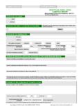
3 (if applicable) Report reference: DOMESTIC Electrical installation - This form is based on the model shown in Appendix 6 of BS 7671 Report pages including inspection and test schedules 1 of 6 SUPPLY CHARACTERISTICS AND EARTHING ARRANGEMENTSTick boxes and enter details, as appropriate Nature of Supply Parameters System Type(s) Number and Type of Live ConductorsNOTES: (1) by enquiry(3) where more than one supply, the higher or highest values(2) by enquiry or by measurement Characteristics of Primary supply Overcurrent Protective Device(s)TN-S TN-C-S TT 1-phase(2 wire) 1-phase(3 wire) 2-phase(3 wire) 3-phase(4 wire) other Nominal Voltage U (1) VNominal frequency f (1) HzU (1) VExternal earth fault loop impedance Ze (3/4) Single-phaseProspective fault current (2/3) kA3- phaseProspective fault current (2/3) kABS(EN)
4 Type Rated current AShort-circuit capacity kAPARTICULARS OF installation AT THE ORIGIN Tick boxes and enter details, as appropriateMeasured Ze Main Switch or circuit-BreakerMeans of earthingDetails of installation Earth Electrode (where applicable)Maximum demand : (load) kVA/AmpsTypeBS(EN) Voltage rating VDistributor's facility Type:(eg rod(s), tape, etc) Location: Number of smoke alarms No of poles RatedCurrent AInstallation earth electrode Electrode resistance, RA: Method of measurement: Protective measures for fault protection Supplyconductormaterial: RCD operating current I n mAEarthing conductorMain protective bonding conductors and bonding of extraneous conductive parts ( )Conductormaterial: Conductormaterial: Conductorcsa: Waterservice Oil service Supply conductorcsa: mm2 RCD operating time (at I n) msConductorcsa: mm2 Continuity check ( ) Location:(where not obvious) Gasservice Structuralsteel Other service SCHEDULE OF ITEMS TESTEDNote.
5 All boxes must be completed External earth loop impedance, Ze Polarity Protection by separation of circuits installation earth electrode resistance, Ra Earth fault loop impedance Zs Other (*Please note below) Continuity of protective conductors Verification of phase sequence * Further notes for items tested, if applicable Continuity of ring final circuit conductors Operation of residual current device(s) Insulation resistance between live conductors Functional testing of assemblies Insulation resistance between live conductors and earth Verification of voltage drop Report reference: DOMESTIC Electrical installation - This form is based on the model shown in Appendix 6 of BS 7671 Report pages including inspection and test schedules 2 of 6 SCHEDULE OF ITEMS INSPECTED Note.
6 All boxes must be completedProtective measures against electric shockAdditional protectionCables and conductorsBasic and fault protectionExtra low voltageDouble or reinforced insulation SELV Presence of residual current devices(s) Selection of of conductors for current carrying capacity and voltage drop Double or reinforced insulation Presence of supplementary bonding conductors Erection methodsBasic protectionPrevention of mutual detrimental influences Routing of cables in prescribed zones Insulation of live parts Barriers and enclosures Proximity of non- Electrical services and other influences Cables incorporating earthed armour, sheath or run in an earthed wiring system, or otherwise protected against nails.
7 Screws and the likeFault protection Segregation of band I and band II circuits or band II insulation used Additional protection by 30mA RCD (where required in premises not under the supervision of skilled or instructed persons)Automatic disconnected of supply Segregation of safety circuits Connection of conductors Presence of earthing conductorsIdentification Presence of fire barriers, suitable seals and protection against thermal effects Presence of circuit protection conductors Presence of diagrams, instructions, circuit charts and similar informationGeneral Presence of main protective bonding conductors Presence of danger notices Presence and correct location of appropriate devices for isolation and switching Choice and setting of protective devices (for fault protect and/or overcurrent)
8 Presence of other warning notices, including presence of mixed wiring colours Adequacy of access to switchgear and other equipmentElectrical separation Labelling of protective devices, switches and terminals Particular protective measures for special Installations and locations For one item of current -using equipment Identification of conductors Connection of single pole devices for protection or switching in line conductors only Correct connection of accessories and equipment To indicate that an inspection or test has been carried out and the result is satisfactoryN/VTo indicate that details could not be verified Selection of equipment and protective measures appropriate to external influencesXTo indicate that an inspection or test has been carried out and the result was
9 UnsatisfactoryN/ATo indicate the inspection or test is not applicable Selection of appropriate functional switching devices Report reference: DOMESTIC Electrical installation - This form is based on the model shown in Appendix 6 of BS 7671 Report pages including inspection and test schedules 3 of 6 TEST INSTRUMENTS USEDE arth fault loop impedance Insulation resistance Continuity RCD Other Other NOTES FOR RECIPIENTTHIS CERTIFICATE IS A VALUABLE DOCUMENT AND SHOULD BE RETAINED FOR FUTURE
10 REFERENCEThis safety certificate has been issued to confirm that the Electrical installation work to which it relates has been designed, constructed and inspected and tested in accordance with British Standard 7671 (The IEE Wiring regulations). You should have received an original Certificate and the contractor should have retained a duplicate Certificate. If you were the person ordering the work, but not the owner of the installation , you should pass this Certificate, or a full copy of it including the schedules immediately to the original certificate should be retained in a safe place and be shown to any person inspecting or undertaking further work on the Electrical installation in the future.