Transcription of design example of six storey building - IIT Kanpur
1 Document No. :: Final Report :: A - Earthquake Codes IITK-GSDMA Project on building Codes design example of a Six storey building by Dr. H. J. Shah Department of Applied Mechanics M. S. University of Baroda Vadodara Dr. Sudhir K Jain Department of Civil Engineering Indian Institute of Technology Kanpur Kanpur This document has been developed under the project on building Codes sponsored by Gujarat State Disaster Management Authority, Gandhinagar at Indian Institute of Technology Kanpur . The views and opinions expressed are those of the authors and not necessarily of the GSDMA, the World Bank, IIT Kanpur , or the Bureau of Indian Standards. Comments and feedbacks may please be forwarded to: Prof. Sudhir K Jain, Dept.
2 Of Civil Engineering, IIT Kanpur , Kanpur 208016, email: design example of a building Page 3 example Seismic Analysis and design of a Six storey building Problem Statement: A six storey building for a commercial complex has plan dimensions as shown in Figure 1. The building is located in seismic zone III on a site with medium soil. design the building for seismic loads as per IS 1893 (Part 1): 2002. General1. The example building consists of the main block and a service block connected by expansion joint and is therefore structurally separated (Figure 1). Analysis and design for main block is to be performed.
3 2 The building will be used for exhibitions, as an art gallery or show room, etc., so that there are no walls inside the building . Only external walls 230 mm thick with 12 mm plaster on both sides are considered. For simplicity in analysis, no balconies are used in the building . 3. At ground floor, slabs are not provided and the floor will directly rest on ground. Therefore, only ground beams passing through columns are provided as tie beams. The floor beams are thus absent in the ground floor. 4. Secondary floor beams are so arranged that they act as simply supported beams and that maximum number of main beams get flanged beam effect. 5. The main beams rest centrally on columns to avoid local eccentricity. 6. For all structural elements, M25 grade concrete will be used.
4 However, higher M30 grade concrete is used for central columns up to plinth, in ground floor and in the first floor. 7. Sizes of all columns in upper floors are kept the same; however, for columns up to plinth, sizes are increased. 8. The floor diaphragms are assumed to be rigid. 9. Centre-line dimensions are followed for analysis and design . In practice, it is advisable to consider finite size joint width. 10. Preliminary sizes of structural components are assumed by experience. 11. For analysis purpose, the beams are assumed to be rectangular so as to distribute slightly larger moment in columns. In practice a beam that fulfils requirement of flanged section in design , behaves in between a rectangular and a flanged section for moment distribution. 12.
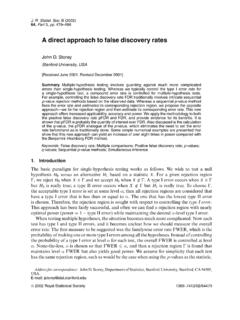
5 In Figure 1(b), tie is shown connecting the footings. This is optional in zones II and III; however, it is mandatory in zones IV and V. 13. Seismic loads will be considered acting in the horizontal direction (along either of the two principal directions) and not along the vertical direction, since it is not considered to be significant. 14. All dimensions are in mm, unless specified otherwise. design example of a building Page 4 ( , )(15, )( , )(0,0)( ,0)14C(15,0)15C( ,0)16C( , )12C( ,15)8C(0,15)(0, )5C9C6CC7( , )(15, )11C(15, 15)( ,15)C10Z(0, ) mAService m1 m5 m5 m5 m5 m5 m+ + mGround Floor+ mFirst Floor+ m Second Floor+ mThird Floor+ mFourth Floor+ mFifth Floor+ m+ mTie5 m5 m5 m5 m5 m+ m+ m+ m+ m+ m+ m+ mM25M25M25M25M25M25+ mM25(a) Typical floor plan(b) Part section A-A(c) Part frame sectionyxA1234567X1 CMain blockStorey numbers300 600600 600300 600500 500 Expansion Figure 1 General lay-out of the building .
6 design example of a building Page 5 Data of the example The design data shall be as follows: Live load : kN/m2 at typical floor : kN/m2 on terrace Floor finish : kN/m2 Water proofing : kN/m2 Terrace finish : kN/m2 Location : Vadodara city Wind load : As per IS: 875-Not designed for wind load, since earthquake loads exceed the wind loads. Earthquake load : As per IS-1893 (Part 1) - 2002 Depth of foundation below ground : m Type of soil : Type II, Medium as per IS:1893 Allowable bearing pressure : 200 kN/m2 Average thickness of footing : m, assume isolated footings storey height : Typical floor: 5 m, GF: m Floors : + 5 upper floors.
7 Ground beams : To be provided at 100 mm below Plinth level : m Walls : 230 mm thick brick masonry walls only at periphery. Material Properties Concrete All components unless specified in design : M25 grade all Ec = 5 000ckf N/mm2 = 5 000ckf MN/m2 = 25 000 N/mm2 = 25 000 MN/m2. For central columns up to plinth, ground floor and first floor: M30 grade Ec = 5 000ckf N/mm2 = 5 000ckf MN/m2 = 27 386 N/mm2 = 27 386 MN/m2. Steel HYSD reinforcement of grade Fe 415 confirming to IS: 1786 is used throughout. Geometry of the building The general layout of the building is shown in Figure 1. At ground level, the floor beams FB are not provided, since the floor directly rests on ground (earth filling and 1:4:8 at plinth level) and no slab is provided. The ground beams are design example of a building Page 6 provided at 100 mm below ground level.
8 The numbering of the members is explained as below. storey number storey numbers are given to the portion of the building between two successive grids of beams. For the example building , the storey numbers are defined as follows: Portion of the building storey no. Foundation top Ground floor 1 Ground beams First floor 2 First Floor Second floor 3 Second floor Third floor 4 Third floor Fourth floor 5 Fourth floor Fifth floor 6 Fifth floor - Terrace 7 Column number In the general plan of Figure 1, the columns from C1 to C16 are numbered in a convenient way from left to right and from upper to the lower part of the plan. Column C5 is known as column C5 from top of the footing to the terrace level. However, to differentiate the column lengths in different stories, the column lengths are known as 105, 205, 305, 405, 505, 605 and 705 [Refer to Figure 2(b)].
9 The first digit indicates the storey number while the last two digits indicate column number. Thus, column length 605 means column length in sixth storey for column numbered C5. The columns may also be specified by using grid lines. Floor beams (Secondary beams) All floor beams that are capable of free rotation at supports are designated as FB in Figure 1. The reactions of the floor beams are calculated manually, which act as point loads on the main beams. Thus, the floor beams are not considered as the part of the space frame modelling. Main beams number Beams, which are passing through columns, are termed as main beams and these together with the columns form the space frame. The general layout of Figure 1 numbers the main beams as beam B1 to B12 in a convenient way from left to right and from upper to the lower part of the plan.
10 Giving 90o clockwise rotation to the plan similarly marks the beams in the perpendicular direction. To floor-wise differentiate beams similar in plan (say beam B5 connecting columns C6 and C7) in various floors, beams are numbered as 1005, 2005, 3005, and so on. The first digit indicates the storey top of the beam grid and the last three digits indicate the beam number as shown in general layout of Figure 1. Thus, beam 4007 is the beam located at the top of 4th storey whose number is B7 as per the general layout. Gravity Load calculations Unit load calculations Assumed sizes of beam and column sections are: Columns: 500 x 500 at all typical floors Area, A = m2, I = m4 Columns: 600 x 600 below ground level Area, A = m2, I = m4 Main beams: 300 x 600 at all floors Area, A = m2, I = m4 Ground beams: 300 x 600 Area, A = m2, I = m4 Secondary beams: 200 x 600 Member self- weights.