Transcription of DESIGN FOR SHEAR2008
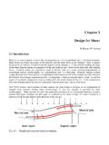
1 Dr. Mohammed E. Haque, PE. Shear DESIGN Page 1 of 6. DESIGN FOR SHEAR. Max. Shear due to loads, Vu DESIGN Shear Capacity, Vn Where = DESIGN Shear Capacity, Vn = [ DESIGN Shear strength of concrete, Vc + DESIGN Shear strength of reinforcement , Vs ]. Vn = Vc + Vs Therefore, Vu [ Vc + Vs ]. Shear force that concrete can resist without web reinforcement , Vc (ACI Eq. ) Vc = 2 fc' (bw x d ). where fc' is in psi; bw and d are in inches 1 Vu bw 45 0 d 1 Section 1-1. d Fig. 1. Dr. Mohammed E. Haque, PE. Shear DESIGN Page 2 of 6. d s Number of stirrups crossing the crack, n=d/s Vu 45 0. Fig. 2. Vs = Av x fy x n Vs = Av x fy x d/s (ACI ).
2 S = Av x fy x d / Vs where Av = cross-sectional area of each stirrup has crossed the crack Av = 2 times the cross-sectional area of the stirrup bar. Av = 3 times the cross-sectional area of the stirrup bar. Fig. 3. Dr. Mohammed E. Haque, PE. Shear DESIGN Page 3 of 6. Fig. 4 Flow Chart Vertical Shear reinforcement DESIGN (Dr. Mohammed E. Haque, ). Known: fc', fy, d, bw and Vu = = 1 for normal weight concrete; for Vc = 2 fc'. bw d sand-lightweight concrete; for all lightweight concrete Vs = [Vu - Vc] Yes Section should be 8 fc'. bw d < [ Vs ] enlarged. No No No shear Determine spacing of reinforcement is vertical U stirrups based Vu > Vc on minimum shear necessary reinforcement Determine Yes required spacing of vertical U.
3 Stirrups based on No Yes Vs Vu > Vc S is smaller of the two: S = Av fy d /[Vu - Vc]. S = Av fy /[50 bw] S must be S = Av fy /[ fc' . bw] S d/2 24 in S must be If [Vu - Vc] > 4 fc'. bw d S d/2 24 in S d/4. Draw the beam and show reinforcement and spacing Dr. Mohammed E. Haque, PE. Shear DESIGN Page 4 of 6. A. d Support A. width = w1 d Section A-A. bw of Symmetry wu A B. L. RA = wu x L /2 RB = wu x L /2. d + w1. RA. Vu at Critical Section Shear carried by Vu - Vc stirrups Vs Vu Shear carried by concrete Vc Vc Vc Minimum Shear reinforcement Shear reinforcement required Shear reinforcement not required Fig. 5 Shear reinforcement requirements Dr.
4 Mohammed E. Haque, PE. Shear DESIGN Page 5 of 6. Summary (Vertical Stirrup or Web reinforcement DESIGN ). 1. Draw Shear, Vu Diagram (Fig. 5). 2. Calculate Vu at a distance d from the face of support 3. On the Vu diagram, identify locations where (1) Shear reinforcement required, (2) where shear reinforcement not required, (3) where shear carried by stirrups, Vs , and (4) where minimum shear reinforcement required (Shear carried by concrete, Vc ). [Note: SEE Fig. 5]. 4. Calculate Vc = 2 fc' (bw x d), where = ;. = 1 for normal weight concrete; for sand-lightweight concrete; for all lightweight concrete. 5. Calculate Vs = [Vu - Vc].
5 Check: If 8 fc'. bw d < [ Vs ], then SECTION SHOULD BE ENLARGED [STOP AT THIS STEP]. 6. No Stirrups are needed if Vu < Vc DESIGN STIRRUPS. 7. Determine required spacing of vertical U stirrups based on Vs Calculate theoretical stirrup spacing, S = Av x fy x d / [Vu - Vc]. S must satisfy S d/2 24 inch If [Vu - Vc] > 4 fc'. bw d Then S d/4. Dr. Mohammed E. Haque, PE. Shear DESIGN Page 6 of 6. 8. Determine spacing of vertical U stirrups based on minimum shear reinforcement . S is smaller of the two: S = Av fy /[50 bw]. S = Av fy /[ fc' . bw]. S must satisfy S d/2 24 inch 9. Minimum practical stirrup spacing is 3 to 4 inches.
6 10. Draw the beam and show the shear reinforcements and spacing.





![A arXiv:1611.09940v3 [cs.AI] 12 Jan 2017](/cache/preview/0/5/e/3/b/3/5/a/thumb-05e3b35a82d1f81c3b8d7fe81db68158.jpg)