Transcription of Design Manual Horizontal Alignment Chapter 2 …
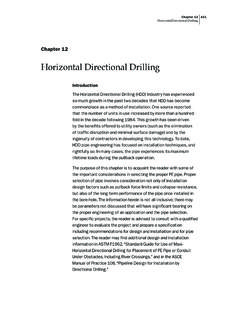
1 Page 1 of 6 This section addresses the following: Horizontal curves, Design considerations, and Plan curve data. Simple Horizontal Curves A simple circular curve is a constant radius arc used to join two tangents. Figure 1 shows the components of a simple Horizontal curve. Figure 1: Components of a simple Horizontal curve. Compound Horizontal Curves Compound Horizontal curves consist of two curves joined at a point of tangency and on the same side of a common tangent. Though their radii are in the same direction, they are of different values.
2 The most commonly used compound Horizontal curve designs are two-centered and three-centered. Figure 2 illustrates two- and three-centered compound Horizontal curves. Curves may have four or more centers; Horizontal Alignment 2A-1 Design Manual Chapter 2 Alignments Originally Issued: 09-22-00 Revised: 07-22-14 Office of Design Quick Tips: A formal Design exception for Horizontal alignments refers only to the Horizontal curvature. Horizontal Alignment influences other controlling criteria ( , Design speed, stopping sight distance, and superelevation).
3 Refer to Section 6D-1 for criteria on measuring sight distance on Horizontal curves. Refer to Section 2A-2 for superelevation criteria. Chapter 2 Alignments Section 2A-1 Horizontal Alignment Page 2 of 6 however, these are complicated to compute and stake. Three curves is considered a practical limit for compound Horizontal curves. Figure 2: Components of two- and three-centered compound Horizontal curves. Definitions PI = Point of Intersection of back tangent and forward tangent. PC = Point of Curvature. This is the point of change from back tangent to circular curve.
4 PCC = Point of Compound Curvature for compound Horizontal curves. PT = Point of Tangency. This is the point of change from circular curve to forward tangent. LC = Total chord length, or long chord, from PC to PT in feet for the circular curve. D = Degree of curvature. The central angle which subtends a 100 foot arc, see Figure 1. The degree of curvature is determined by the appropriate Design speed. = Intersection (or delta) angle between back and forward tangents. I = Total intersection angle of a compound Horizontal curve. fl = Intersection angle (decimal degrees) of the flattest curve of a compound Horizontal curve.
5 Md = Intersection angle (decimal degrees) of the middle curve of a compound Horizontal curve. sh = Intersection angle (decimal degrees) of the sharpest curve of a compound Horizontal curve. T = Tangent distance in feet. The distance between the PC and PI or the PI and PT. TL = Long Tangent of a compound Horizontal curve. TS = Short Tangent of a compound Horizontal curve. X = Distance from PC to PT of a compound Horizontal curve in the direction of the backward tangent. Y = Perpendicular distance of a compound Horizontal curve from the backward tangent to the PT.
6 L = Total length in feet of the circular curve from PC to PT measured along its arc. E = External distance (radial distance) in feet from PI to the mid-point of the circular curve. Chapter 2 Alignments Section 2A-1 Horizontal Alignment Page 3 of 6 R = Radius of the circular curve measured in feet. The radius is determined by the appropriate Design speed: Sections 1C-1, 2A-2, and 2A-3 of this Manual provide further information, or refer to AASHTO s A Policy on Geometric Design of Highways and Streets. Rfl = Radius of the flattest curve of a compound Horizontal curve.
7 Rmd = Radius of the middle curve of a compound Horizontal curve. Rsh = Radius of the sharpest curve of a compound Horizontal curve. = Deflection angle from a tangent to a point on the circular curve. /2 = Deflection angle for full circular curve measured from tangent at PC or PT. C = Chord length in feet, where a chord is defined as a straight line connecting any two points on a curve. S = Arc length in feet along a curve. MO = Middle ordinate. Length of the ordinate from the middle of the curve to the LC. Formulas D = R18000 (D in decimal degrees, English units only) =RL180 ( in decimal degrees) L = 180R ( decimal in degrees) R = L180 ( in decimal degrees) T = R 2tan ( in decimal degrees) E = T 4tan ( in decimal degrees) LC = 2 R 2sin ( in decimal degrees) MO = R 2cos1 ( in decimal degrees) C = 2 R 2sin ( in decimal degrees) S = 2 RCarcsin90R Two-centered Compound Curves I = fl + sh X = Rsh sin(I) + (Rfl Rsh) sin( fl) Y = Rfl Rsh cos(I) (Rfl Rsh)
8 Cos( fl) TL = )Isin()cos()RR()Icos(RRshshflflsh + Chapter 2 Alignments Section 2A-1 Horizontal Alignment Page 4 of 6 TS = )Isin()cos()RR()Icos(RRflshflshfl sin fl = shflshSLRR)Isin(R)Icos(TT + sin sh = shflSLflRRT)Icos(T)Isin(R Three-centered Compound Curves I = fl + md + sh X = )Isin(R)sin()RR()sin()RR(shmdflshmdflmdf l+ + + Y = )cos()RR()cos()RR()Icos(RRmdflshmdflmdfl shfl + TL = )Isin()cos()RR()cos()RR()Icos(RRshshmdsh mdmdflflsh + + + TS = )Isin()cos()RR()cos()RR()Icos(RRmdflshmd flmdflshfl + Design Considerations Several items should be considered in the process of designing a Horizontal curve.
9 Horizontal Sight Distance Physical features along the inside of a curve can restrict sight distance. Refer to Section 6D-1 for measuring sight distance along the inside of a curve. Superelevation Refer to Section 2A-2 and Section 2A-3 for superelevation rates and transitions. Refer to Section 2A-4 for superelevation transition considerations for pavement drainage. Minimum Radius Avoid the use of the minimum radius for Design . Actual speeds exceeding the Design speed increase the potential for trucks overturning and run-off-the-road crashes.
10 Additionally, drivers will track a path sharper than the real radius of a curve. Spiral Curve Transitions Use spiral curve transitions for high-speed roadways. Drivers gradually turn into curves, with the path following a spiral curve. Roadway segments with spiral curve transitions have the potential for fewer crashes than segments without spiral curve transitions. Refer to Section 2C-1 for spiral curves. Coordination with Vertical Alignment Do not Design Horizontal and vertical alignments separately. Horizontal and vertical curves superimposed upon one another ( , Horizontal and vertical PIs at about the same stations) limit the number of sight distance restrictions.