Transcription of CHAPTER 6 VERTICAL ALIGNMENT
1 6-1 CHAPTER 6 VERTICAL ALIGNMENT Introduction 6-3 VERTICAL ALIGNMENT Controls 6-3 Figure 6-1 Contrast of Poor Grade Line Design (Left) with Preferred Grade Line Design (Right) Figure 6-2 Example of a Hidden Dip Figure 6-3 Broken Back (Left) Versus Smooth Continuous (Right) Grade Line Figure 6-4 Balanced VERTICAL and Horizontal Alignments Figure 6-5 Landscape Backdrop is also a Safety Feature Figure 6-6 Example of Undesirable Effect of a Profile on a Pronounced Crest Figure 6-7 Simultaneous VERTICAL and Horizontal Curvature Maximum Grades 6-8 Table 6-1 Maximum Grades on Construction/ Reconstruction Projects for Interstate and State Highways Table 6-2 Maximum Grades on Construction/Reconstruction Projects for Urban Arterials Table 6-3 Maximum Grades for 3R Projects on the National Highway System other than the Interstate Table 6-4 Maximum Grades for 3R Projects other than the National Highway System Minimum Grades 6-10 Minimum Ditch Grades
2 6-10 VERTICAL Curves 6-11 Figure 6-8 Types of VERTICAL Curves Figure 6-9 General Properties of VERTICAL Curves Figure 6-10 Relationship between VERTICAL Curve Properties and Sight Distance Table 6-5 Stopping Sight Distance for Crest VERTICAL Curves Table 6-6 Stopping Sight Distance for Sag VERTICAL Curves Table 6-7 Passing Sight Distance Figure 6-11 Method of Locating and Determining the Limits of No-Passing Zones of VERTICAL and Horizontal Curves Table 6-8 Percent Restricted Passing Lengths 6-2 Urban Design 6-20 Gradeline Elevations 6-22 Figure 6-12 Railroad Highway Grade Crossing Climbing Lane Criteria 6-26 Figure 6-13 Critical Length Computations Truck Escape Ramp Criteria 6-29 Figure 6-14 Escape Ramp Layout 6-3 INTRODUCTION Unless otherwise indicated, the profile grade represents the elevation of the top of the subgrade at the roadway centerline.
3 Finished gradeline and elevations will be shown on the plans for bridge replacement and urban grading projects. For divided highways a VERTICAL ALIGNMENT should be shown on the plans for each direction of travel. The profile grade line is a series of tangents connected by parabolic arcs. The point where tangents intersect is known as the VERTICAL point of intersection ( ). The stationing of each is identified to the nearest 1 (urban) or 10 (rural) intervals and the elevation should be identified to the nearest . The slope or grade of each tangent is expressed in percent rise (+) or fall (-) to the forth decimal place. Each parabolic VERTICAL curve is identified by a curve length, usually defined to the nearest one hundred feet. VERTICAL ALIGNMENT CONTROLS Terrain Terrain classifications (level, rolling, or mountainous) pertain to the general character of a specific route corridor.
4 Selection of terrain is somewhat objective, but is normally an obvious choice. The project can include more than one terrain based on the character of the existing terrain however route continuity should be reviewed. South Dakota s river breaks may be considered rolling or mountainous where steeper grades are necessary. Ties with Adjoining Projects A smooth transition shall be provided to adjoining projects. Therefore, adequate space shall be provided on the plans to plot the survey lines into adjoining projects for a smooth transition. If the ALIGNMENT of the adjoining project is inadequate by present standards, use a connecting grade which can be utilized when the adjoining project is reconstructed and which satisfactorily adjoins the existing ALIGNMENT . To obtain a smooth transition to adjoining projects, a spline curve may be required.
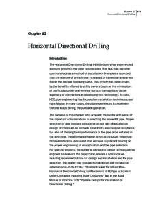
5 A spline curve is produced by plotting an exaggerated VERTICAL scale profile (for example 1" = 1' VERTICAL and 1" = 50' horizontal). By doing this, a blown up version of the tie-in situations created and can be viewed with detail. Then points can be established along a curve that 6-4smoothly transitions into the existing highway. When a spline curve is used, show the roadway elevations every 25' on the profile. A spline curve would not be required if the design gradeline could be tied into the existing surface with a 1 in 40 rate of change tolerance. Smooth Grade Line To obtain a smooth grade line, changes in grade should be gradual and consistent with the type of highway and the character of the terrain as shown in Figure 6-1. Numerous breaks and short lengths of grade tangents should be avoided.
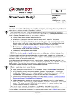
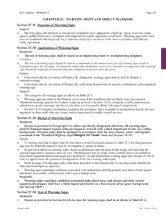
6 Figure 6-1 Contrast of Poor Grade Line Design (Left) with Preferred Grade Line Design (Right) Hidden Dips The "roller coaster" or "hidden dip" type of profile should be avoided as shown in Figure 6-2. Often they are proposed in the interest of economy, but they are aesthetically undesirable and extremely hazardous. Figure 6-2 Example of a Hidden Dip 6-5 Broken Back Grade Lines Avoid "broken back" grade lines (two crest or sag VERTICAL curves separated by a short tangent as shown in Figure 6-3. One long VERTICAL curve is more desirable. In sag VERTICAL this is particularly noticeable and not pleasing to the eye. If a broken back curve is unavoidable, it is desirable to provide at least a 400 tangent between two VERTICAL curves. Figure 6-3 Broken Back (Left) Versus Smooth Continuous (Right) Grade Lines Intersecting Road Where at-grade-intersections occur on roadway sections with moderate to steep grades, it is desirable to reduce the gradient through the intersection.)
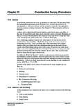
7 Such a profile change is beneficial for all vehicles making turns and serves to reduce the potential hazards. Intersecting roads (county on and off system roads) may be designed to a 40 mph design speed. Some situations may require the design speed to be reduced. The Secondary & Off-System Road Plan which is an agreement between the FHWA and SDDOT is available in the Secondary Roads Office. This agreement establishes design standards for county on and off system roads. Coordination of Horizontal & VERTICAL ALIGNMENT The proper relationships between VERTICAL and horizontal curvature result in an aesthetic and easy-to-drive facility. On the other hand, there are some relationships or combinations which make driving more difficult and less safe. The horizontal and VERTICAL alignments should be in balance as shown in Figure 6-4.
8 A generous flowing ALIGNMENT in one plane is not compatible with small and frequent breaks in the other. 6-6 Figure 6-4 Balanced VERTICAL and Horizontal Alignments A road at the crest which disappears into the sky as shown in Figure 6-5 can be disconcerting to the driver. It would be more appealing to have the view above the crest backed by a backdrop of landscape. Figure 6-5 Landscape Backdrop is also a Safety Feature A profile on a pronounced crest along a horizontal curve as shown in Figure 6-6, particularly in flat terrain, tends to produce in a foreshortened view a disturbingly awkward appearance. Use of longer and flatter approach gradients, coupled with special grading and planting on inside of the curve may reduce the undesirable effect. 6-7 Figure 6-6 Example of Undesirable Effect of a Profile on a Pronounced Crest Avoid simultaneous VERTICAL and horizontal curvatures shown in Figure 6-7 wherever possible.
9 When unavoidable, make sure that the curve lengths - both VERTICAL and horizontal - are well above the minimum permitted by standards. When horizontal and VERTICAL curves are in the same location, the horizontal and VERTICAL curve geometrics ( VERTICAL and horizontal PI Sta's and curve lengths) should be similar. Figure 6-7 Simultaneous VERTICAL and Horizontal Curvature Balancing Earthwork Usually, projects should be designed to produce balanced earthwork. Excavated material from within the limits of the regular typical section should be the amount needed to construct embankments to the designed grade. This can be approximated by placing a template of the typical roadway section on the cross sections at several points and adjusting the height of the template until cut and fill appear to be balanced.
10 These elevations marked on the working profile will help establish a proper grade for balance. Subsequent slight modifications of profile grade often are necessary to attain desired frequent balance points of one half mile or less desired and one mile maximum. 6-8 Adjusting the profile grade up or down is one way of balancing the earthwork so that excavation within the roadway prism will be adequate to construct the designed embankments. In some instances, particularly in rolling or mountainous terrain, this is practical as long as the previously mentioned criteria for gradeline elevations are not compromised. To reduce or eliminate the amount of borrow material needed on a project, consideration should be given to deeper cuts, wider or deeper ditch bottoms, and/or flattening or daylighting the backslopes in cut areas where feasible.