Transcription of Design No. U311
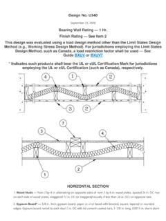
1 Design No. U311 September 23, 2020 Bearing Wall Rating 1 HR. Finish Rating 23 Min. This Design was evaluated using a load Design method other than the Limit States Design Method ( , Working Stress Design Method). For jurisdictions employing the Limit States Design Method, such as Canada, a load restriction factor shall be used See Guide BXUV or BXUV7 * Indicates such products shall bear the UL or cUL Certification Mark for jurisdictions employing the UL or cUL Certification (such as Canada), respectively. 1. Wood Studs Nom 2 by 4 in., spaced 16 or 24. OC. Effectively cross braced. 2. Resilient Channel 25 MSG galv steel. Resilient channels spaced vertically 24 in.
2 OC, flange portion screw attached to one side of studs with 1-1/4 in. long Type W coarse thread gypsum panel steel screws. 2A. Steel Framing Members* (Optional, Not Shown, As an alternate to Item 2) As an alternate to Item 2, furring channels and Steel Framing Members as described below: a. Furring Channels Formed of No. 25 MSG galv steel. 2-9/16 in. or 2-23/32 in. wide by 7/8 in. deep, spaced 24 in. OC perpendicular to studs. Channels secured to studs as described in Item b. Ends of adjoining channels are overlapped 6 in. and tied together with double strand of No. 18 SWG galv steel wire near each end of overlap. As an alternate, ends of adjoining channels may be overlapped 6 in.
3 And secured together with two self-tapping #6 framing screws, min. 7/16 in. long at the midpoint of the overlap, with one screw on each flange of the channel. b. Steel Framing Members* Used to attach furring channels (Item a) to studs (Item 1). Clips spaced 48 in. OC. and secured to studs with No. 8 x 2-1/2 in. coarse drywall screw through the center grommet. Furring channels are friction fitted into clips. RSIC-1 clip for use with 2-9/16 in. wide furring channels. RSIC-1 ( ) clip for use with 2-23/32 in. wide furring channels. PAC INTERNATIONAL L L C Types RSIC-1, RSIC-1 ( ). 2B. Steel Framing Members* (Optional, Not Shown, As an alternate to Item 2) Furring channels and Steel Framing Members as described below: a.
4 Furring Channels Formed of No. 25 MSG galv steel. 2-3/8 in. wide by 7/8 in. deep, spaced 24 in. OC perpendicular to studs. Channels secured to studs as described in Item b. Ends of adjoining channels are overlapped 6 in. and tied together with double strand of No. 18 SWG galv steel wire near each end of overlap. As an alternate, ends of adjoining channels may be overlapped 6 in. and secured together with two self-tapping #6 framing screws, min. 7/16 in. long at the midpoint of the overlap, with one screw on each flange of the channel. Gypsum board attached to furring channels as described in Item 3. b. Steel Framing Members* Used to attach furring channels (Item a) to studs.
5 Clips spaced 48 in. OC. Genie clips secured to studs with No. 8 x 1-1/2 in. coarse drywall screw through the center hole. Furring channels are friction fitted into clips. PLITEQ INC Type Genie Clip 2C. Steel Framing Members* (Optional, Not Shown, As an alternate to Item 2) Furring channels and Steel Framing Members as described below: a. Furring Channels Formed of No. 25 MSG galv steel. Spaced 24 in. OC perpendicular to studs. Channels secured to studs as described in Item b. Ends of adjoining channels overlapped 6 in. and tied together with double strand of No. 18 AWG galvanized steel wire. Gypsum board attached to furring channels as described in Item 3.
6 B. Steel Framing Members* Used to attach furring channels (Item 2Ca) to studs. Clips spaced 48 in. OC., and secured to studs with 2 in. coarse drywall screw with 1 in. diam washer through the center hole. Furring channels are friction fitted into clips. STUDCO BUILDING SYSTEMS RESILMOUNT Sound Isolation Clips Type A237R 2D. Steel Framing Members* (Optional, Not Shown, As an alternate to Item 2) Furring channels and Steel Framing Members as described below: a. Furring Channels Formed of No. 25 MSG galv steel. Spaced 24 in. OC perpendicular to studs. Channels secured to studs as described in Item 2Db. Ends of adjoining channels overlapped 6 in.
7 And tied together with double strand of No. 18 AWG galvanized steel wire. Gypsum board attached to furring channels as described in Item 3. b. Steel Framing Members* Used to attach furring channels (Item 2Da) to studs. Clips spaced 48 in. OC., and secured to studs with No. 8 x 2-1/2 in. coarse drywall screw through the center hole. Furring channels are friction fitted into clips. REGUPOL AMERICA Type SonusClip 2E. Steel Framing Members* (Optional, Not Shown, As an alternate to Item 2) Resilient channels and Steel Framing Members as described below: a. Resilient Channels Formed of No. 25 MSG galv steel, spaced 24 in. OC, and perpendicular to studs.
8 Channels secured to studs as described in Item b. Ends of adjoining channels overlapped 6 in. and secured in place with two No. 8 15 x 1/2 in. Philips Modified Truss screws spaced 2-1/2 in. from the center of the overlap. Gypsum board attached to resilient channels as described in Item 2. b. Steel Framing Members* Used to attach resilient channels (Item 2Ea) to studs. Clips spaced 48 in. OC., and secured to studs with No. 8 x 2-1/2 in. coarse drywall screw through the center hole. Resilient channels are secured to clips with one No. 10 x 1/2 in. pan-head self-drilling screw. KEENE BUILDING PRODUCTS CO INC Type RC+ Assurance Clip 2F. Steel Framing Members* (Optional, Not Shown, As an alternate to Item 2) Furring channels and Framing Members as described below: a.
9 Furring Channels Formed of No. 25 MSG galv steel. Spaced 24 in. OC perpendicular to studs. Channels secured to studs as described in Item 2Fb. Ends of adjoining channels overlapped 6 in. and tied together with double strand of No. 18 AWG galvanized steel wire. As an alternate, ends of adjoining channels may be overlapped 6 in. and secured together with two self-tapping No. 6 framing screws, min. 7/16 in. long at the midpoint of the overlap, with one screw on each flange of the channel. Two layers of gypsum board attached to furring channels as described in Item 3A. b. Framing Members* Used to attach furring channels (Item 2Fa) to studs (Item 1).
10 Rafts secured to stud, spaced a maximum of 24 in. OC. horizontally, vertically spaced 3 in. from the top and bottom and 24 inch on center along each stud and secured with two 1-1/4 inch (No. 6) Type W drywall screws. One on each side of the core. Fasteners should not be placed closer than 1/4 inch to the edges of the mounts. BCD LLC Type HushFrame Raft Connector 2G. Steel Framing Members* (Optional, Not Shown, As an alternate to Item 2) Used as an alternate method to attach resilient channels to wall studs. A resilient sound isolation accessory shall be used at each attachment point of the resilient channels and spaced max 16 or 24 in.