Transcription of Design of fillet welds and N partial penetration butt welds
1 24 NSCJune 16 TechnicalIntroductionA simple rule of thumb approach to sizing partial penetration butt welds carrying longitudinal shear has sometimes been used where the resistance is based on the average shear stress used for checking the shear resistance of beam webs: in BS 5950 or fy/ 3 in EN 1993-1-1. This confusingly led to a lower shear resistance than that found when sizing the weld using the specified Design strength. In what follows, the directional method in EN 1993-1-8 is discussed and examples of weld Design are presented, showing the rule of thumb approach to be conservative and methodThe directional method for Design of fillet welds and partial penetration butt welds in EN 1993-1-8 clause involves checks of 1) combined stress and 2) direct stress on the weld throat and compares each with a different limiting stress denoted here by the general term L.
2 The limiting stresses are based on the ultimate strengths of the material (which are constant for most thicknesses up to 100 mm) and the values for different steel grades are given in the table below. The stresses are in MPa. A material factor of (for bridges) has been used. In the directional method for the Design of fillet welds , direct stresses perpendicular and parallel to the weld throat are denoted in clause (4) and so are shear stresses in the plane of the weld throat. Direct stresses parallel to the axis of the weld are not considered further.
3 The orientations of the stresses are shown in Figure formula in EN 1993-1-8 is 2pr + 3( 2pr + 2pl) L() (1)where the direct stress is perpendicular to the weld throat and the shear stresses are in the perpendicular (transverse) and parallel (longitudinal) directions. In equation (1), the subscript pr has been used instead of the EN 1993-1-8 symbol and pl instead of || . In designing partial penetration butt welds , the designer determines the penetration required and the fabricator chooses the weld preparation to achieve the penetration specified, based on his welding processes and the corresponding weld Mises failure criterionThe EC3 formula for the combined stress on a weld is based on the Von Mises failure criterion which is usually expressed in terms of principal stresses (orientated such that there are no coincident shear stresses).
4 The standard expression is: ( 1 2)2 + ( 2 3)2 + ( 3 1)2 2 L2 where 1 , 2 and 3 are the principal stresses in three orthogonal directions and L is a limiting stress. In the Design of joints with essentially linear welds between plates, the stress in the through thickness direction is zero (see figure 2) so for the biaxial stress state, the equation becomes: ( 1 2)2 + 22 + ( 1)2 2 L2 (2) The failure criterion in equation (2) is expressed in terms of principal stresses which are related to coincident direct and shear stresses using the transformation equations illustrated by Mohr s circle of of fillet welds and partial penetration butt weldsRichard Henderson of the SCI discusses the directional method for the Design of fillet welds and partial penetration butt welds and shows how the combined stress formula is related to Von Mises failure criterion.
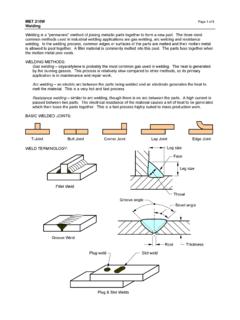
5 The weld Design rules can be applied in all 1 Limiting stresses in fillet welds in EN 1993-1-8 Steel gradeS235S2751,2S3551S4201S4601 strengthfu360410470520540 Limiting combined stressfu/( w M2)360386418416432 Limiting direct M22592953383743891 Subgrade M has minimum tensile strengths which vary with thicknesses below 100 mm2 Subgrades M and N have a minimum tensile strength of 370 MPaFigure 1 Stresses on the weld throatFigure 2: Stresses in plate elementsPurchase your copy:@SCIsteelsteel-construction-institu teSCI Shop: : | Telephone: 01344 636505 NEW SCI Bridging in Light Steel Framing & Modular Construction (P411)Buildings account for nearly half of the UK s total carbon emissions and heat losses through the building envelope account for more than 75% of the total heat loss including air leakage.
6 In response to the Energy Performance of Buildings Directive and the UK Climate Change Act 2008, national regulations are requiring ever more energy efficient s newest publication illustrates various cases of thermal bridging and how local heat losses can be reduced. It describes the results of thermal modelling analyses of typical interface details used in light steel framing and modular publication focusses on thermal bridging at junction details and balcony support attachments. The information may be used as general guidance on how to minimise thermal bridging in light steel framing and modular publications include; P402 Light Steel Framing in Residential ConstructionP410 Thermal Bridging in Steel ConstructionED019 Thermal Performance of Light Steel ConstructionPublication costs.
7 SCI Members - Members - 16In general, orthogonal stresses x and y and coincident shear stress xy are present and principal stresses are given by: 1 = + 2xy x+ y2+ x y2()2 2 = + 2xy x+ y2 x y2()2where the square root term is the radius of the Mohr s circle and its centre is at ( x + y). If the transformations are made, the formulae in equations (1) and (2) are algebraically identical when y equals stressesThe Von Mises failure criterion is often expressed in terms of the yield strength of the material.
8 However, in the Eurocode, in the Design of fillet welds and partial penetration butt welds , as we have seen in Table 1, for lower steel grades, the limiting strength is allowed to be a higher value, between the yield strength and the ultimate strength of the material. Interestingly, for higher strength steels, the inclusion of the material factor of means that the limiting stress is less than the yield strength of the material. For S355 steel, the limiting direct stress is less than the yield strength for material 40 mm thick or less.
9 Engineers who remember designing to BS 5950-1: 1990 will recall the requirement to check the stress on the fusion line of partial penetration butt welds and limit it to in shear or in tension. This check was no longer a requirement in the 2000 update of the code. Comparisons of the limiting shear stress with the values for combined stress assuming pure shear (ie pr in equation (1) is zero) in Table 2 show that the limiting stresses in the Eurocode are higher for the lower strength grades and lower for the higher strength (1) A weld in pure shear is carrying a force of kN/mm in grade S355 material.
10 A partial penetration Vee butt weld is to be used. What depth of weld penetration is required? The shear stress on the weld of 250 MPa gives a weld throat to BS 5950 of mm. Design to BS 5950: 1990 used a Design strength pw of 255 MPa on the weld throat. However the shear stress on the fusion line was also limited to = 249 MPa resulting in the same weld size . Using the directional method in EC3, all the components of stress are zero except for the shear stress parallel to the axis of the weld ( pl) so substituting in equation (1), the Design shear stress is 418/ 3 MPa (241 MPa) and the weld size is the principal stresses are calculated in each case, we find the following for the weld to BS 5950: 2000.