Transcription of design - polypipe.com.au
1 Pipe Systems PE Pipe Systems PE Pipe Systems PE Pipe Systems PE Pipe Systems PE Pipe Systems PE Pipe SystemsdesigncontentsPipe Selection3 Pipe Dimensions4 Allowable Operating Pressure5 Temperature Influences7 Service Lifetimes7 Pipe design for Variable Operating Conditions8E Modulus10 Selection of Wall thickness for Special Applications10 Hydraulic Design11 Flow Chart Worked Examples13 Part Full Flow15 Resistance Coefficients16 Flow Charts17-26 Surge and Fatigue27 Celerity28 Slurry Flow29 Pipe Wear30 Maintenance and Operation31 Fittings31 Pneumatic Flow32 System design Guidelines for the Selection of Vinidexair Compressed Air Pipelines33 Expansion And Contraction35 External pressure Resistance36 Trench Design37 Allowable Bending Radius38 Deflection Questionnaire FAX BACK39 Deflection Questionnaire Vinidex locations40 Thrust Block Supports41 Electrical Conductivity43 Vibration43 Heat Sources43 Irrigation Warehouse Group Pty 1300 661 417PE Pipe Systems PE Pipe Systems PE Pipe Systems PE Pipe Systems PE Pipe Systems PE Pipe Systems PE Pipe of LiabilityThis manual has been compiled by Vinidex PtyLimited ( the Company )
2 To promote betterunderstanding of the technical aspects of theCompany s products to assist users in obtainingfrom them the best possible manual is supplied subject toacknowledgement of the following conditions: The manual is protected by Copyright and maynot be copied or reproduced in any form or byany means in whole or in part without priorconsent in writing by the Company. Product specifications, usage data and advisoryinformation may change from time to time withadvances in research and field experience. TheCompany reserves the right to make suchchanges at any time without notice. Correct usage of the Company s productsinvolves engineering judgements which cannotbe properly made without full knowledge of allthe conditions pertaining to each specificinstallation.
3 The Company expressly disclaimsall and any liability to any person whethersupplied with this publication or not in respectof anything and of the consequences of anythingdone or omitted to be done by any such personin reliance whether whole or partial upon thewhole or any part of the contents of thispublication. No offer to trade, nor any conditions of trading,are expressed or implied by the issue of contentof this manual. Nothing herein shall override theCompany s Conditions of Sale, which may beobtained from the Registered Office or any SalesOffice of the Company. This manual is and shall remain the property ofthe Company, and shall be surrendered ondemand to the Company. Information supplied in this manual does notoverride a job specification, where such conflictarises, consult the authority supervising the job.
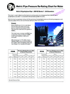
4 Copyright Vinidex Pty LimitedABN 42 000 664 942 Irrigation Warehouse Group Pty 1300 661 Pipe Systems PE Pipe Systems PE Pipe Systems PE Pipe Systems PE Pipe Systems PE Pipe Systems PE Pipe SystemsdesignPipe SelectionVinidex PE pipes are available in acomprehensive range of sizes up to1000mm diameter, and pressure classesin accordance with the requirements ofAS/NZS 4130 - Polyethylene (PE) pipesfor pressure sizes and pressure classes toAS/NZS 4130 requirements are addedfrom time to time and subject tominimum quantity requirements, pipesmade to specific sizes, lengths orpressure classes are Standard AS/NZS 4130 includes arange of PE material designations basedon the Minimum Required Stress (MRS),and classified as PE63, PE80, andPE100.
5 When pipes are made to thesame dimensions, but from differentrated PE materials, then the pipes willhave different pressure relationship between the dimensionsof the pipes, the PE materialclassification and the working pressurerating are as shown in Table simplicity, the dimensions of the pipehave been referred in terms of theStandard Dimension Ratio (SDR) where:Outside DiameterSDR =Wall ThicknessTable Comparison of SDR & pressure Ratings (PN) PN16PN20PN25 Notes:PELong term rupture stress at 20 C (MPa x 10) to which a minimum design factoris applied to obtain the 20 C hydrostatic design hoop pressure rating at 20 C (MPa x10).SDRN ominal ratio of outside diameter to wall Warehouse Group Pty 1300 661 417PE Pipe Systems PE Pipe Systems PE Pipe Systems PE Pipe Systems PE Pipe Systems PE Pipe Systems PE Pipe DimensionsTable PE Pipe Dimensions AS/NZS 4130 NominalSizeDNSDR 41 SDR 33 SDR 26 SDR 21 SDR 17 SDR 11 SDR 9 SDR WallThickness(mm) (mm)Min.
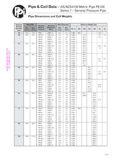
6 WallThickness(mm) (mm)Min. WallThickness(mm) (mm)Min. WallThickness(mm) (mm)Min. WallThickness(mm) (mm)Min. WallThickness(mm) (mm)Min. WallThickness(mm) (mm)Min. WallThickness(mm) (mm)Min. WallThickness(mm) (mm) Pipe Dimensions (based on AS/NZS 4130-1997, Polyethylene pipes for pressure applications.)SDR Nominal ratio of outside diameter to wall thickness . ID internal diameterIrrigation Warehouse Group Pty 1300 661 Pipe Systems PE Pipe Systems PE Pipe Systems PE Pipe Systems PE Pipe Systems PE Pipe Systems PE Pipe SystemsdesignAllowableOperating PressureHydrostatic design BasisVinidex pipes manufactured to AS/NZS4130, Series 1 have wall thickness andpressure ratings determined by theBarlow formula as follows.
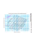
7 T = minimum wall thickness (mm)P = normal working pressureof pipe(MPa)D = minimum mean OD(mm)S = hydrostatic design stressat 20 C(MPa)See Table design StressThe design of AS/NZS 4130 pipes hasbeen based on the static workingpressure operating continuously at themaximum value for the entire lifetime ofthe value of maximum hoop stress usedin the selection of the pipe wall thicknessis known as the Hydrostatic DesignStress (S). This value is dependent uponthe type of PE material being used andthe pipe material service temperature. InAS/NZS 4131, materials are classified forlong term strength by the designationMinimum Required Strength (MRS).The MRS is the value resulting fromextrapolation of short and long termtests to a 50 year point at 20 : See Figure for typical stressregression Hydrostatic design Stress andMinimum Required Strength ValuesMaterial DesignationMinimum Required StrengthHydrostatic design Stress(MRS) MPa(S) standard values are polymerdependent and long term properties foreach pipe grade material are establishedby long term testing to the requirementsof ISO/DIS 9080 by the polymerproducers.
8 Individual PE grades mayexhibit different characteristics and PEmaterials can be provided with enhancedspecific properties. In these cases theadvice of Vinidex engineers should AllowableOperating PressurewhereMAOP is the maximum allowableoperating pressure in is the pipe classification inaccordance with AS/NZS is the design example, if the minimum value of F ischosen (F = ), a PN10 pipe will havea MAOP of MPa at 20 +PS=MRSFMAOP=PN x Hydrostatic design Stress (S) isobtained by application of a design orSafety Factor (F) to the Table specific value selected for theDesign Factor depends on a number ofvariables, including the nature of thetransmitted fluid, the location of thepipeline, and the risk of third wall thickness values for Series 1pipes to AS/NZS 4130 were derivedusing a value of for F, this being theminimum value 4131 specifics MRS values MPa, MPa and MPa for thegrades designated as PE63.
9 PE80 andPE100 relationship between the S and MRSstandard values in AS/NZS 4131 is asshown in Table Warehouse Group Pty 1300 661 417PE Pipe Systems PE Pipe Systems PE Pipe Systems PE Pipe Systems PE Pipe Systems PE Pipe Systems PE Pipe design Factors Gas PipesInstallationConditionsDesign Factor ValueFluid typeNatural FormStraight Temperature (Av. C)-10 < t < 0 < t < 20 < t < 30 < t < Crack density & area loadingOpen trafficed roads in inbuilt trafficed roads in inbuilt in populated in industrial area area : Where factor values are not listed, consult with Vinidex engineers installation applications are usedto carry fluids other than water, thenanother value of the design Factor mayneed to be selected.
10 The value selectedwill depend on both the nature of thefluid being carried and the location of thepipeline installation. For specificinstallations, the advice of Vinidexengineers should be the case of gas pipes in AS/NZS 4130,both Series 2 and Series 3, a DesignFactor ranging between F = andF = applies depending on the specificinstallation conditions; see Table design FactorsPipeline ApplicationDesign Factor20 CFWater the design Factor is varied, thenthe MAOP for the particular Series 1 pipePN rating can be calculated as follows:In the particular case of gas distribution,then the type of gas, and the pipelineinstallation conditions need to beconsidered. In this case the DesignFactor is a combination of a number ofsub factors (fx) which must be factoredtogether to give the final value for F suchthat:F = f0 x f1 x f2 x f3 x f4 x f5 MAOP=PN x PE Pipe pressure RatingsPN Rating NumberNominal Working PressureMPaHead MetresPN 8 10 16 20 Warehouse Group Pty 1300 661 Pipe Systems PE Pipe Systems PE Pipe Systems PE Pipe Systems PE Pipe Systems PE Pipe Systems PE Pipe SystemsdesignTemperatureInfluencesThe physical properties of Vinidex PEpipes are related to a standard referencetemperature of 20 C.