Transcription of Detecting Power Grid Synchronization Failure on …
1 International Journal of Research in Advent Technology, , , April 2016 E-ISSN: 2321-9637 Available online at 220 Detecting Power grid Synchronization Failure on Sensing Frequency or Voltage beyond Acceptable Range Laukik S. Raut1, Shahrukh B. Pathan2, Gaurav N. Pawar3, Mandar V. Pathak4 Department of Electrical engineering1, 2, 3, 4, , 2, 3, 4 Email: , Abstract- The system to detect the Synchronization Failure of any external supply source to the Power grid on sensing the abnormalities in frequency and voltage. There are several Power generation units connected to the grid such as tidal, thermal, solar etc to supply Power to the load.
2 These generating units need to supply Power according to the rules of the grid . These rules involve maintaining a voltage variation within limits and also the frequency. If any deviation will occurs then automatically disconnect the grid line. This prevents in large scale brown out or black out of the grid Power . So it is preferable to have a system which can warn the grid in advance so that alternate arrangements are kept on standby to avoid complete grid Failure . This system is based on a microcontroller of 8051 family. The microcontroller monitors the under/over voltage being derived from a set of comparators. As the frequency of the mains supply cannot be changed, so by using variable frequency generator (555-timer) frequency can changed.
3 A lamp load (indicating a predictable blackout, brownout) being driven from the microcontroller in case of voltage/frequency going out of acceptable range. Keywords: Frequency, grid , Power , Synchronization , Voltage. 1. INTRODUCTION In day to day life electrical energy has evolved as one of the most basic needs of human being. As we know that electricity generated at generating station will be transferred to required location accounting into various losses. Though still it is not assured to transfer with required efficiency it is proved to be economical ,as well as it will carry more losses, interruptions, voltage and frequency fluctuations.
4 The seminar report suggests about designed to develop a system to detect the Synchronization Failure that means in Power distribution systems, the Power grid station gets supply from different feeder stations like a thermal Power station, a wind Power station, a solar Power station etc. For feasible transmission, the frequency and voltage of the AC supply should be within the limits as decided by the grid . In this seminar grid is depending upon the demand of the Power supply. There are several Power generation units connected to the grid such as hydro, thermal, solar etc. to supply Power to the load.
5 These generating units need to supply Power according to the rules of the grid . These rules involve maintaining a voltage variation within limits and also the frequency. This prevents in large scale brown out or black out of the grid Power . So it is preferable to have a system which can warn the grid in advance so that alternate arrangements are kept on standby to avoid complete grid Failure . In case these limits are exceeded and the demand for Power is more than the demand for supply, it results in grid Failure . In such situations, the feeder unit is completely disconnected from the grid , causing islanding situation.
6 Thus Synchronization is needed between the grid and the feeder unit. This paper defines a way to detect the variations in frequency and voltage of the Power supply from the feeder unit to determine the Synchronization Failure . Here a frequency variation detection system and a voltage variation detection system are used. For frequency variation, voltage variations, and for the current variations we uses the sensors here. In case of any voltage ,frequency variations, the lamp is switched on .of any external supply source to the Power grid on sensing the abnormalities in frequency and voltage.
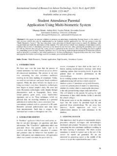
7 Block Diagram International Journal of Research in Advent Technology, , , April 2016 E-ISSN: 2321-9637 Available online at 221 : Block Diagram of solar based automatic plant watering system In this paper we will use Microcontroller 8051, LCD, ADC. 0809, Relay, Lamp, Sensor etc .in block diagram. ADC 0809 have in build 8:1 multiplexer it supposed to interface 8 different analog input connected to the analog input channel reference to above to analog input connected to the input no. (IN0&IN1) Select the line used to select desire analog input channel & here they are kept at Ground level to select is by using sensor device.
8 From which frequency, voltage can be is the start of conversion signal to initiate the conversion process and EOC indicate conversion over . EOC =1,the converted digital available at respective port. : LCD Pin Description 1. VVCC,VSS,VEE While VCC & VSS provide +5v &ground is used for controlling the LCD contrast. 2. RS (Register select) There are two important register inside the LCD if, RS=0 a command code register is selected allowing the user to send command such as clear display, cursor at home etc. If, RS=1 data register is selected allowing user to send a data to be display on the LCD unit.
9 3. RR/W(Read/Write) R/W input allows the user to write the information to the LCD or read the information from it. R/W=1 when reading. R/W=0 when writing. 4. (Enable) Enable is for latch the information presented to its data pins when the data is supplied to the data pin a high to low pulse must be applied to this pin in order for the LCD to latch in data present at the data pins. 5. D0-D7 The 8 bit data pins D0-D7 are used to send the information to the LCD internal register .To display the letter , numbers we send the ASCII codes of these letters numbers. These are also instruction command codes that can be send to the LCD such as clear display unit force the cursor to home position ,bring the cursor.
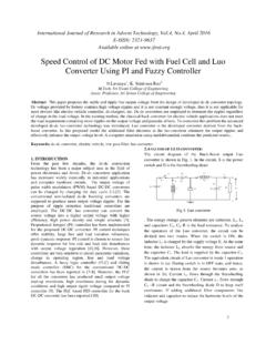
10 : Relay driver ULN2803 APG Fig. 2: Relay driver ULN2803 APG The ULN2803 APG / AFWG Series are high voltage, high current drivers comprised of eight NPN pairs. All units feature integral clamp diodes for switching inductive loads. Applications include relay, hammer, lamp and display (LED) drivers. The suffix (G) appended to the part number represents a Lead Free product. : Features of Relay Driver 1. Output current (single output) 500 mA (Max.) 2. High sustaining voltage output 50 V (Min.) 3. Output clamp diodes 4. Inputs compatible with various types of logic. 5. Package Type APG : DIP 18pin : Problems Detected At Power grid International Journal of Research in Advent Technology, , , April 2016 E-ISSN: 2321-9637 Available online at 222 The main aim of this seminar is to develop design develop a system to detect the Synchronization Failure of any external supply source to the Power grid on sensing the abnormalities in frequency and voltage.