Transcription of Development of a Dropped Weight Impact Testing …
1 International Journal of Engineering & Technology IJET-IJENS Vol: 11 No: 06 98 115606-9393 IJET-IJENS @ December 2011 IJENS I J E N S Abstract This article presents the Development of a Dropped Weight Impact Testing machine. The machine was developed as a facility to provide experimental data to validate numerical simulations of Impact loads on crash boxes, parts of car structure that absorb kinetic energy during collision. The Dropped Weight Impact machine was designed to produce Impact load to a specimen that represents a crash box. The machine was equipped with sensor systems to measure the velocity of the impactor just before it hit the specimen and the force that crushed the specimen, and with a data acquisition system to record the crushing force for further analysis.
2 The Development process included the design, fabrication, and function tests of the machine. The function tests performed after the machine was built indicated that the Dropped Weight Impact Testing machine can fulfill the design objectives. Results of several experiments using specimens in form of columns with square, hexagonal, octagonal and circular cross sections showed that the experimental results are in good agreements with the results of Impact simulations carried out using Finite Element Method. Index Term Crash box, design, Impact load, experiments. I. INTRODUCTION One of the main concerns in traffic safety nowadays is the improvement of the vehicle crashworthiness. To increase passenger safety, some parts of automotive structure known as crash boxes are designed to absorb kinetic energy during collision.
3 These components are usually in the form of columns which will undergo progressive plastic deformation during collision. The crushing force, the force needed to deform the crash box, determines the deceleration of the vehicle during collision and indicates the capability of the crash box to absorb kinetic energy. The value of crushing force is determined by the geometry and the material of the crash box. Several researches on the analyses of buckling behavior of prismatic columns under low velocity Impact have been reported for several years [1, 2, 3, 4, 5, 6]. These earlier studies explored columns of different materials and geometries which were unrelated from one to another. Hence, it is not easy to obtain certain relation between columns geometry and material with their capability to absorb Impact energy.
4 Practical researches that produced usable design rules are limited. Further, for columns made of aluminum, which is of LeonardoGunawan is with the Faculty of Mechanical and Aerospace Engineering, Institut Teknologi Bandung, Bandung 40132, Indonesia ( e-mail: Tatacipta Dirgantara is also with the Faculty of Mechanical and Aerospace Eng., ITB, Bandung 40132, Indonesia (e-mail: Ichsan Setya Putra is also with the Faculty of Mechanical and Aerospace Eng., ITB, Bandung 40132, Indonesia (e-mail: importance in the future due to its high strength to Weight ratio, only a few results have been published. From these considerations, systematic studies on energy absorption capacity of prismatic aluminum columns under low speed Impact were carried out [7, 8, 9, 10, 11]. In these studies, behavior of aluminum columns subjected to axial Impact load were numerically analyzed using explicit finite element method.)))
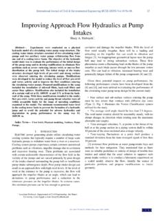
5 Parameters considered in this study were cross section geometry and wall-thickness to perimeter ratio. Fig. 1 shows a result of numerical simulation of an aluminum circular tube subjected to axial Impact load [7]. To verify the results of these numerical studies, an Impact Testing machine based on Dropped Weight principle was developed. The Impact speed obtained from this principle is limited by the dropping height. However, the range of the Impact speed still fulfills the low speed criteria. Moreover, its Development and operation cost is low. This article presents the design and Testing of this machine. II. DESIGN OF LOW VELOCITY Impact Testing MACHINE A. Design Objectives The Impact Testing machine was designed to perform low speed Impact tests, Impact velocities less than 15 m/s. At each Impact speed, the kinetic energy should be able to be varied.
6 The machine should be able to accommodate Impact tests on specimens of various cross sectional geometry with maximum outer geometry of 60 mm and maximum height of 170 mm. Other considerations in design were the safety and cost aspects. B. Conceptual Design An Impact machine based on Dropped Weight principle was selected since it is able to provide Impact velocity by using earth gravity. This machine is a cost effective solution compared to that using a gas gun. In the design, a specimen was fixed on top of a steel base. An impactor was elevated and then released at a certain height above the specimen. The impactor would hit the specimen with an Impact speed that depends on the dropping height. The kinetic energy of the impactor was then absorbed by the progressive folding of the specimen wall, which reduced the kinetic energy of the impactor until it finally stopped.
7 Development of a Dropped Weight Impact Testing Machine Leonardo Gunawan, Tatacipta Dirgantara, and Ichsan Setya Putra International Journal of Engineering & Technology IJET-IJENS Vol: 11 No: 06 99 115606-9393 IJET-IJENS @ December 2011 IJENS I J E N S The crushing force of the specimen during the Impact was sensed by using a load cell which was placed between the specimen and the steel base. The crushing force data was then recorded by a data acquisition system. A speed sensor was used to measure the speed of the impactor just before hitting the specimen. The crushing force data, the Dropped Weight mass and the Impact speed were used in the validation of numerical analysis.
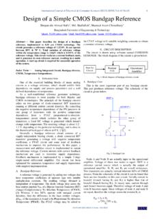
8 From the design principle and requirements, the Dropped Weight Impact Testing machine was designed. Based on the design objectives and following [12, 13], several designs were considered and the best solution according to some previously set criteria was selected. Fig. 2 shows schematically the final design of the Impact Testing machine which can be divided into 4 subsystems, namely: the frame that consists of guide columns, base plate and concrete block; the impactor assembly that consists of impactor frame, projectile, roller, and weighting mass; the clamp and hoist mechanism; and the instrumentation. Frame The columns were designed to act as a guide of the moving impactor assembly. Two columns guide design was selected from three alternatives: no column, one column and two columns. The two columns guide design was selected due to its safety, moderate price and easiness of operation.
9 The columns were made of 6 m long stainless steel pipe, with outer diameter of mm and thickness of 6 mm. They were mounted on top of a base plate made of 3 cm thick steel. The base plate was fixed on top of a 1 m 1 m 2 m concrete block. The concrete block was half-buried in a square hole with width of m and depth of m on the floor. The hole was at first filled with m thick sand and then the concrete block was put inside the hole. Finally, the gap between the hole and block was filled with sand. The sand would isolate the shock and vibrations during the experiment to the neighborhood. Impactor Assembly The impactor assembly consisted of an impactor frame, an Impact head, weighting masses and rollers. The rollers were attached to the frame and each roller was equipped with a pretension spring that kept the roller always in contact with the guide column.
10 This mechanism ensured that the impactor assembly always moved along the guide column during the experiments. The Impact head was designed to be the part of the impactor assembly that hit the specimen. The mass of the frame, roller and Impact head without the weighting masses was 20 kg. The mass of the impactor assembly could be adjusted by adding several weighting masses until the total mass of the impactor assembly was 150 kg. If there is no significant friction working on the rollers, the impactor assembly will hit the specimen with a speed of: gHv2 (1) Although the length of the guide columns was 6 m, the maximum dropping height of the impactor was less than 6 m since some space should be provided for the specimen, the load cell, the hoist, the clamp and the impactor assembly itself. The maximum effective height for the impactor was 5 m which corresponds to a maximum Impact velocity of m/s.
![IJENS-RPG [IJENS Researchers Promotion Group] ID: …](/cache/preview/1/7/b/a/8/0/e/3/thumb-17ba80e3168c7f59c03bc21e79d7d2ee.jpg)