Transcription of Development of Next-Generation Large-Scale SOFC …
1 Mitsubishi Heavy Industries Technical Review Vol. 52 No. 2 (June 2015) 111 *1 Senior Manager, Fuel Cell Business Department, Mitsubishi Hitachi Power Systems, Ltd. *2 Deputy General Manager, Fuel Cell Business Department, Mitsubishi Hitachi Power Systems, Ltd. *3 Group Manager, Fuel Cell Business Department, Mitsubishi Hitachi Power Systems, Ltd. *4 Engineering Manager, Boiler Products Headquarters, Mitsubishi Hitachi Power Systems, Ltd. Development of Next-Generation Large-Scale SOFC toward Realization of a Hydrogen Society YOSHINORI KOBAYASHI*1 KAZUO TOMIDA*2 MASANORI NISHIURA*3 KENICHI HIWATASHI*3 HIROSHI KISHIZAWA*3 KOICHI TAKENOBU*4 Mitsubishi Hitachi Power Systems, Ltd.
2 (MHPS) is developing a combined power generationsystem by combining a solid oxide fuel cell (SOFC), which is a fuel cell that can operate at hightemperature, with other power generation systems including gas turbines. For commercial application of the hybrid system, MHI has been conducting demonstration tests at Tokyo Gas Co.,Ltd.'s Senju Techno Station and the operation was started in March 2013. The pressurized-type SOFC-MGT hybrid system brought about by combining the 200-kW-class SOFC with a micro gas turbine (MGT) achieved 4,100 hours of continuous operation for the first time in the world, andexhibited a stable operation state even during the heavy-load season in summer.
3 Based on this accomplishment, a new compact-type demonstration system was designed and set up at nationaluniversity corporation Kyushu University in March 2015. It is planned to be used in demonstrationstudies and basic research in the future. |1. Introduction In order to solve global warming problems, energy problems and economic problems at thesame time, it is indispensable to reduce carbon emissions from energy sources and to increaseefficiency in energy use. Therefore, to reduce emissions of CO2, one of the major greenhouse effect gases, it is necessary to combine decentralized power sources rationally according to location andcapacity on the basis of the present state of an electric power base infrastructure established with acentralized power source of high efficiency thermal power generation, etc.
4 , and then, to introduce new energies including renewable energies in the most economical and rational way possible. And,partly for global preservation of energy resources, it is indispensably and urgently required to usefossil fuel as effectively as possible by developing and quickly diffusing a high efficiency powergeneration system. This article introduces the current Development status of MHPS's SOFC, the status of thedemonstrations of the SOFC-MGT hybrid system, which is a combined power generation system of the SOFC and a MGT, being conducted through the project of the National Research andDevelopment Agency New Energy and Industrial Technology Development Organization (NEDO),and future developments.
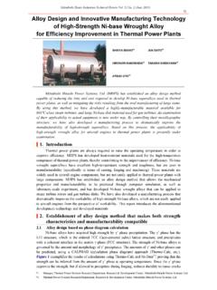
5 |2. Composition of SOFC combined power generation system Cell stack Figure 1 illustrates the structure of a cell stack of MHPS's tubular type SOFC. On the outersurface of the substrate tube, which is a structural member, a cell (anode, electrolyte, and cathode)reacting to generate power is formed and an electron-conductive ceramic used as an interconnector connects these cells in series. By selecting components with similar thermal expansion coefficientsand the adoption of integral sintering through the improvement of manufacturing technology, the production cost has been reduced, the bonding strength of components has been increased, and theperformance and durability have been improved.
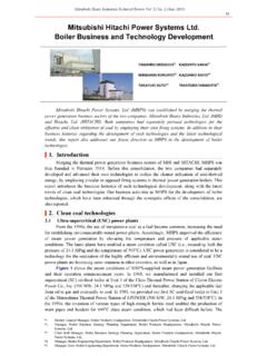
6 Mitsubishi Heavy Industries Technical Review Vol. 52 No. 2 (June 2015) 112 Figure 1 Structure of cell stack MHPS has been developing our own high performance cell stacks. The Model 10 cell stackraised the number of cells to 85, and at the same time, the power output per cell stack has beenenhanced by 30 by optimizing the interconnector composition, adjusting the cathode, etc. In theModel 15 cell stack, with which we have been attempting to further improve efficiency, theinterface between the electrodes and the electrolyte has been improved to further increase theoutput density by 50 compared with Model 10 (Figure 2).
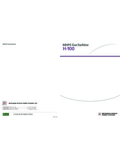
7 Figure 2 Tubular cell stack for SOFC Cartridge A cartridge that outputs electricity of several tens of kW by binding the cell stacks is formedand a set of cartridges with the necessary capacity, which is collectively contained in a pressurevessel, constitutes a module (Figure 3). Figure 3 Composition of SOFC-MGT hybrid system Mitsubishi Heavy Industries Technical Review Vol. 52 No. 2 (June 2015) 113 The adoption of such a layered structure seeks systematization by taking installation andeven maintainability into consideration.
8 In addition, since the electric output can be adjusted by the number of cartridges or the number of modules, a required wide range of electric output can becovered. For the cartridge, higher per unit volume output density is aimed at. The higher packingdensity is accompanied by a higher heating density, but the heat transfer/cooling design of cartridges controls the heat transfer characteristics, ensuring the conventional level of heat transferin the power generating area as well as in the heat exchange area across the power generation Model 15.
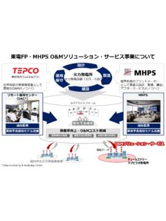
9 The reduction of the diameter and increase of the length of a cell stack enable anincrease in the output density per unit volume and reduction of the system installation area(Figure 4). Figure 4 Development of cell stack/cartridge for low-cost mass production System The hybrid system shown in Figure 5 generates electric power by the SOFC and the MGT in two steps. By installing waste heat recovery equipment on the exhaust gas line, it can function as aco-generation system that supplies steam and hot water at the same time.
10 Figure 5 SOFC-MGT hybrid system |3. Market introduction plan for the hybrid system Demonstration at Tokyo Gas Co., Ltd. (Model 10 demonstration system) Based on the achievements thus far, from fiscal 2011 to 2014, we conducted the Development and evaluation of the Model 10 250 kW-class SOFC-MGT hybrid demonstration system, under the NEDO project at Tokyo Gas Co., Ltd.'s Senju Techno Station. An MGT made by Toyota Turbineand Systems Inc. was adopted (Figure 6). Mitsubishi Heavy Industries Technical Review Vol. 52 No. 2 (June 2015) 114 Figure 6 Model 10 SOFC-MGT hybrid system for demonstration With this demonstration system, we pinpointed problems toward promotion of initialintroduction of the SOFC-MGT hybrid system and the examination of deregulation for promotion of its introduction.