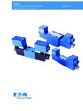
Transcription of DG5S-8 and DG5S-H8 - Vickers伊顿威格士-液压
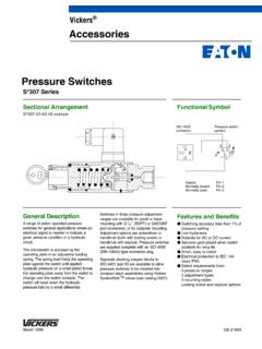
1 vickers . directional Controls DG5S-8 and DG5S-H8 . Two-Stage, Solenoid Controlled, Pilot Operated, Four-Way directional Valves Revised 11/94 591. Introduction General Description Features and Benefits D Fast response and standard low shock models available. The DG5S-8 and DG5S-H8 are D Suitable for the most demanding two-stage directional valves with an industrial applications with DG5S-H8 D Solid cast body and core passages for integrally mounted DG4V3(S) (wet flow capacities up to 530 L/min (140 maximum strength and minimal armature solenoid) pilot valve. USgpm) and rated pressure of 310 bar pressure drop. (4500 psi). These valves are used to control the D High-force solenoids and centering direction of flow in hydraulic circuits. D Available with a wide variety of spool springs assure consistent shifting This directional control in turn provides and spring arrangements, stroke and through a wide range of pressure and control over the movement of a cylinder pilot choke adjustments, integral check silting extremes.
2 Or the rotation of a hydraulic motor. valves, and port orifices. D Designed and backed by vickers , with D Uses vickers DG4V3(S) pilot valve for over 70 years as the global leader in exceptional responsiveness, durability, fluid power and motion control. and ease of servicing. D Numerous electrical options allow full compatibility and easy, reliable connection in any system application. Cross Section of Typical Valve ( DG5S-8 -6B-T-M-U-H5-30). 2. Table of Contents Model Series Recommended Flow Maximum Operating Pressure Page DG5S-8 To 170 L/min (45 USgpm) 210 bar (3000 psi) 4. DG5S-H8 (High Flow) To 265 L/min (70 USgpm) 310 bar (4500 psi) 6. Accessories and Weights 22. Installation and Application Data 24. 3. DG5S-8 Model Series Ratings Maximum Maximum Tank Line Pressure Operating bar (psi).
3 Recommended Press Pressurere M xim m Pilot Maximum Flow* (Ports P, A, & B) Pressure External Drain Internal Drain L/min (USgpm) bar (psi) bar (psi) Models Models Mounting Pattern ISO 4401-08, NFPA D08. To 170 (45) 210 (3000) 210 (3000) 210 (3000) 210 (3000). (formerly D06), and ANSI Maximum flow table see page 8. Model Codes 1 2 3 4 5 6 7 8 9 10 11 12 13 14 15 16 17 18 19 20 21 22 23 24 25. 1 Viton seals 5 Spool/Spring arrangement 8 Response type F3 For mineral oil & fire resistant fluids A Spring offset to A port X Fast response Blank Omit if not required B Spring centered, solenoid A Blank Standard low shock models removed 2 C Spring centered 9. Series designation Spool control modifications D Pressure centered D directional control valve 1 Stroke adjustment both ends F Spring offset to A port, shift G Manifold or subplate mounted 2 Pilot choke (dual) adjustment to center 5 Solenoid controlled, pilot operated 3 Pilot choke and stroke adjustment N No spring detented (pilot only).
4 S Sliding spool, rated pressure 7 Stroke adjustment A port end only 210 bar (3000 psi) 8 Stroke adjustment B port end only 6 Left hand assembly 2-7 Dual pilot choke and stroke 3 L Left hand, single solenoid only. adjustment A port end only Interface Omit if not required. (For right hand 2-8 Dual pilot choke and stroke 8 NFPA D08 (ISO 4401-08). assembly, P to A port when adjustment B port end only solenoid A is energized.) Blank Omit if not required 4 Spool type Blank Omit if not required Code Center position 10 Pilot pressure 0 Open to T all ports 7 Manual override E External pilot pressure 1 Open P & A to T, closed B. Blank Plain override solenoid Blank Internal pilot pressure 2 Closed to T all ports ends only 3 Closed P & B, open A to T. H Waterproof override solenoid **4 Tandem P to T, closed crossover 11 Pilot drain ends only 6 Closed P only, open A & B to T T Internal pilot drain H2 Waterproof override both ends of 7 Open P to A & B, closed T Blank External pilot drain single solenoid **8 Tandem P to T, open crossover P2 Plain override both ends of single 9 Open to T all ports over tapers 12 Pressure port check valve solenoid 11 Open P & B to T, closed A.
5 Y Lockable manual overrides K 0,35 bar (5 psi) cracking pressure 31 Closed P & A, open B to T. solenoid ends only/DC only R 3,45 bar (50 psi) cracking pressure 33 Closed P, open A & B to T. Z No overrides in either end S 5,20 bar (75 psi) cracking pressure over tapers Blank Omit if not required 52 Closed center all ports ** Type 4 and 8 spools may spin within the body causing unusual valve body wear. With this and other spool types, valve malfunction may occur. Where these applications exist use the DG5S-8 *-30/40 EN470 special designator for 4C/8C anti-spin spools/springs. 4. Model Codes (continued). 13 Solenoid energization identity 17 Electrical connections 22 Pilot valve tank pressure rating V Solenoid identification determined (Code F coil only) 2 10 bar (145 psi) DG4V3-60 with by position of solenoid (solenoid A T Wired terminal block S3, S4, or S5 spool indicator at port A end and/or solenoid B at PA Instaplug male receptacle only switch port B end) PB Instaplug male & female receptacle 5 100 bar (1450 psi) DG4V3S-60.
6 Blank Standard arrangement for ANSI PA3 Three pin connector 6 210 bar (3000 psi) DG4V3-60 with (energize solenoid A for flow PA5 Five pin connector AC solenoids and optional S6. P to A port) Blank Omit if not required spool indicator switch (Code V for any valve with code 4 or 7 210 bar (3000 psi) DG4V3-60 with code 8 spool) DC solenoids and optional S6. 18 Housing spool indicator switch (Code F coil only). 14 Flag symbol W 1/2 NPT thread wiring housing M Electrical options and features J 20 mm thread wiring housing 23 Pilot valve port orifices Blank Omit if not required Code Orifice diameter 15 *00 Solid plug Spool indicator switch 19 *03 0,30 mm ( in). (Available on models with high Electrical options *06 0,60 mm ( in). performance pilot DG4V3 only) (Code U coil only). *08 0,80 mm ( in).
7 S3 Normally open (available on 1 ISO with fitted plug *10 1,00 mm ( in). valves with code P* only) 6 ISO with fitted plug and lights *13 1,30 mm ( in). S4 Normally closed (available on *15 1,50 mm ( in). valves with code P* only) 20 Solenoid indicator lights *20 2,00 mm ( in). S5 Free leads (available on (Code F coil with code T electrical *23 2,30 mm ( in). valves with coil type code F only). connections only) Blank Omit if not required S6 LVDT type DC switch with Pg7. L Indicator lights (* = P, T, A, and/or B as required). connector plug Blank Omit if not required 24 Design number 16 Coil type 21 Coil identification 30 DG4V3S-60 pilot valve U ISO 4400. A 110V AC 50 Hz 40 DG4V3-60 pilot valve F Flying lead B 110V AC 50 Hz/120V AC 60 Hz* (Subject to change. Installation SP1 Single 6,3 mm spade to IEC 760.)
8 C 220V AC 50 Hz dimensions same for designs 30 through SP2 Dual 6,3 mm spade to IEC 760. D 220V AC 50 Hz/240V AC 60 Hz* 39 and 40 through 49.). G 12 VDC. H 24 VDC. 25 Special Feature DJ 98 VDC. P 110 VDC. * For 60 Hz or dual frequency 5. DG5S-8 Model Series Performance Characteristics Shift Time Shift Time For AC Models at Rated Flow and Pressure Shift time is defined as the elapsed time (Add approximately 25 milliseconds for DC models). from when the pilot valve solenoid is energized to the time the main stage CENTER TO OFFSET OFFSET TO OFFSET. spool shifts to its full stroke. Shift time (P A or P B) (A B or B A). PILOT PRESSURE psi PILOT PRESSURE psi curves are shown for standard low shock 1000 2000 3000 1000 2000 3000. 120 300. and fast response models at 210 bar 0, 1, 2, 3, 6, 7, 9, 11, 31, 33 & 52.
9 (3000 psi) system pressure with various 100 250. pilot pressures and spools. Pressure 4&8 0, 1, 2, 3, 6, 7, 9, 11, 31, 33 & 52. centering time curves are shown for TIME milliseconds TIME milliseconds 80 200. pressure centered models. Approximate 4&8. spring centering times are also listed for 4&8. 60 150. spring centered models. 4&8. 40 100. Shifting Action The pilot valve solenoids of spring 20 50. centered, pressure centered, and spring 0, 1, 2, 3, 6, 7, 9, 11, 31, 33 & 52. 0, 1, 2, 3, 6, 7, 9, 11, 31, 33 & 52. offset models must be energized 0 70 140 210 0 70 140 210. continuously to keep the main stage PILOT PRESSURE bar PILOT PRESSURE bar spool in the shifted position. No-spring STANDARD LOW SHOCK. detented models only need to be FAST RESPONSE. energized momentarily (for approximately second).
10 Spring Centering Times at Centering Times for Pressure Spring centered and pressure centered Rated Flow and Pressure Centered Valves at Rated models return the valve spool to the Pressure (A P or B P). center position when both solenoids are Spool AC DC. de-energized or pilot pressure fails or Types Models Models PILOT PRESSURE psi 1000 2000 3000. 120. falls below minimum requirements. 2, 3, 6, 7, .050 sec .070 sec Spring offset models return the spool to 31, 33, 52 100. the offset position by pilot pressure when the solenoid is de-energized. 0, 1, 11 .070 sec .100 sec TIME milliseconds 80. 4, 8 .090 sec .120 sec ALL SPOOLS. When no-spring detented models are 60. de-energized, the pilot and main spools 9 .135 sec .160 sec remain in their last position as long as 40. there are no unusual shock, vibration, or pressure transients, and the spool axis is horizontal.


