Transcription of Dial Indicators/Dial Test Indicators
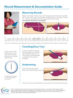
1 20 Quick guide to Precision measuring InstrumentsQuick guide to Precision measuring InstrumentsContinuous dial: For direct readingBalanced dial: For reading the difference from a reference surfaceReverse reading dial: For depth or bore gage measurementOne revolution dial: For error free reading of small differencesDial Indicators /Dial Test Indicators Nomenclature Dial dial (Dual reading)Balanced dial (Multi-revolution)Continuous dial (Reverse reading)Balanced dial (One revolution)Continuous dial (Dual reading)Balanced dial (Multi-revolution)Continuous dial (Double scale spacing)Balanced dial (One revolution)CapBezel clampStemSpindle (or plunger)Contact pointDial faceHand (or pointer)Limit markersBezel21 Quick guide to Precision measuring Instruments Mounting a Dial indicator Dial indicator Contact Point Screw thread section is standardized on (Length: 5mm).
2 Incomplete thread section at the root of the screw shall be less than when fabricating a contact mounting MethodNote Mounting hole tolerance: 8G7(+ to ) Clamping screw: M4 to M6 Clamping position: 8mm or more from the lower edge of the stem Maximum clamping torque: 150N cm when clamping with a single M5 screw Note that excessive clamping torque may adversely affect spindle movement. Mounting hole tolerance: 8G7(+ to )Lug mountingMethodNote Lugs can be changed 90 degrees in orientation according to the application. (The lug is set horizontally when shipped.) Lugs of some Series 1 models (Nos.)
3 1911, 1913-10, & 1003), however, cannot be altered to horizontal. To avoid cosine-effect error, ensure that a dial indicator is mounted with its spindle in line with the intended measurement direction. Dial gage and Digimatic indicator positions Setting the origin of a Digimatic indicatorRepeatability in the range of mm from the end of the stroke is not guaranteed for Digimatic Indicators . When setting the zero point or presetting a specific value, be sure to lift the spindle at least mm from the end of the stroke. Notes on using dial gages and Digimatic Indicators Do not lubricate the spindle.
4 Doing so might cause dust to accumulate, resulting in a malfunction. If the spindle movement is poor, wipe the upper and lower spindle surfaces with a dry or alcohol-soaked cloth. If the movement is not improved by this cleaning, contact Mitutoyo for point down (normal position) Spindle horizontal(lateral position)If measurement is performed with the spindle horizontal or contact point up, the measuring force is less than when the contact point is down. In this case be sure to check the operation and repeatability of the indicator or digital guaranteed-operation specifications according to positions of Digimatic Indicators and dial gages, refer to the product descriptions in a general point up (upside-down position)
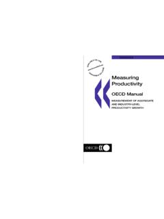
5 Clamping the stem directly with a screwClamping the stem by split-body fastening8mm or morePlain washerM6 3 counterbore, depth , depth 7mm thread section shall be less than guide to Precision measuring InstrumentsQuick guide to Precision measuring InstrumentsDial Indicators /Dial Test Indicators Dial indicator B7503-1997 (Extract from JIS/Japanese Industrial Standards) methodDiagram of calibration setupTools for calibration1 Indication errorHolding the dial indicator with its spindle set vertically downward, follow the procedure prescribed below and determine the error of indication with reference to the dial , displace the spindle upward over the entire measuring range while plotting errors at every 1/10 revolution of the pointer for the first two revolutions from the zero point, at every half revolution for the next five revolutions, and at every revolution after the fifth revolution.
6 Then reverse the spindle displacement at the end of the measuring range of the dial indicator and plot errors at the same points measured during upward spindle displacement. Determine errors from a bidirectional error curve thus obtained. (Fig. 1)For or graduation dial Indicators with a 2mm measuring range or less: A micrometer head or other measuring unit with m graduation or less and instrumental error of 1 m and a supporting dial Indicators other than the above: A micrometer head or other measuring unit with 1 m graduation or less and 1 m instrumental error and a supporting error3 Retrace error4 RepeatabilityApply the contact point of the dial indicator perpendicularly to the upper face of a measuring stage, displace the spindle quickly and slowly five times at a desired position within the measuring range and deter-mine the maximum difference between the five indications obtained.
7 measuring stageSupporting stand5 measuring forceHolding a dial indicator with its spindle set vertically downward, displace the spindle upward and then downward continuously and gradually and take measurements of the measuring force at the zero, middle, and end points in the measuring range in both the upward and downward standTop pan type spring scale (graduation: 2gf or less) or force gage (sensitivity: or less)Graduation and measuring range10mm or less2mm or lessOver 2mm and up to 10mm1mm or lessOver 1mm and up to 2mmOver 2mm and up to 5mmRetrace error1/10 revolution * revolution 9 5 6 3 5 6 One revolution 10 6 7 4 6 7 Two revolutions 15 6 8 4 6 8 Entire measuring range 15 7 12 5 7 10 Maximum permissible error of indicationUnit: m*1: Adjacent accuracyRemarks: Values in the table above apply at at 20 : Maximum permissible errors of a dial indicator shall comply with the table above.
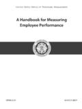
8 Permissible errors of indication shall be evaluated inclusive of the uncertainty of standDial indicatorMicrometer head or other length measuring unitSupporting standMeasuring stage Dial indicatorTop pan type spring scaleDial indicatorSupporting +10 m+10 range2 revolutionsRange for two-revolution indication error and adjacent errorRange for 1/2-revolution indication errorTwo-revolution indication errorAdjacent errorOne-revolution indication error1/2-revolution indication error1/5-revolution or moreEnd pointStrokeRest point of the long pointerZero point1/10-revolution or moreRetraceForwardRetrace errorIndication error Indication error over the entire measuring range10 revolutionsRange for one-revolution indication error23 Quick guide to Precision measuring methodDiagram of calibration setupTools for calibration1 Wide-range accuracy(1) For an indicator of mm graduation.
9 Displace the contact point so as to move the pointer clockwise in increments of mm with reference to the graduations from the zero point to the end point of the measuring range while taking readings of the calibration tool at each point and determine this accuracy from the error curve drawn by plotting the differences of each " indicator reading - calibration tool reading".(2) For an indicator of mm graduation: Displace the contact point so as to move the pointer clockwise in increment of mm with reference to the graduations from the zero point to the end point of the measuring range while taking readings of the calibration tool at each point and determine this accuracy from the error curve drawn by plotting the differences of each " indicator reading - calibration tool reading".
10 The instrumental error of the calibration tool shall be compensated prior to this head or measuring unit (graduation: 1 m or less, instrumental error: within 1 m), sup-porting stand2 Adjacent error3 Retrace errorAfter the completion of the wide-range accuracy measurement, reverse the contact point from the last point of measurement while taking readings at the same scale graduations as for the wide-range accuracy measurement and determine the retrace error from the error curve the dial test indicator with its stylus parallel with the top face of the measuring stage, displace the contact point quickly and slowly five times at a desired position within the measuring range and determine the maximum difference in stage, Support-ing stand.