Transcription of DIAX02 DDS02.1/03.1 Drive Controller - Basic Unit
1 Drive Controller - Basic Planning ,44 Drive Controller - Basic UnitProject Planning ,44 Mappe 11a 209-0069-4317-02 This electronic document based on the hardcopy document with docu-ment desig.: designation of previous edi-tionsStatusComments209-0069-4317-01 931st 941st 97rev. ,44 Apr. 97E-Doc Release INDRAMAT GmbH, 1993 Copying this document, and giving it to others and the use or communi-cation of the contents thereof without express authority are are liable for the payment of damages. All rights are reservedin the event of the grant of a patent or the registration of a utility model ordesign (DIN 34-1).
2 The electronic documentation (E-doc) may be copied as often as neededif such are to be used by the consumer for the purpose GmbH 2 D-97816 Lohr a. MainTelefon 09352/40-0 Tx 689421 Fax 09352/40-4885 Abt. ENA (JH)Service-Hotline: Tel. 0172 - 660 040 6 or 0171 - 333 882 6 All rights are reserved with respect to the content of this documentationand the availability of the of documentationDocument codeInternal file referenceReferenceEditing sequenceCopyrightPublished ,44 IContents1 Introducing the Individual components of the digital AC servo Supply units for Drive 1-22 Safety guidelines for electrical General Guidelines for protection against contact with electrical parts.
3 Guidelines on "protective low voltages".. Guidelines for protection against dangerous movements .. Guidelines for protection when handling and installing .. 2-53 Drive Configured Drive controllers .. Drive Controller , Basic unit .. 3-4 Cooling 3-4 Motor Software module .. Firmware Plugin Configuration rating plate .. Summary of components fitted in a configuration .. 3-134 Technical Power section .. Current consumed during signal Ambient and environmental conditions .. Drive Controller energy loss .. 4-5 Energy loss in the 4-5 Energy loss in the .. 4-6 Energy loss in the .. 4-7 Energy loss in the Weight .. 4-85 Planning the construction of the control Mounting the Drive Mounting the Drive Controller .
4 Mounting the Drive Controller .. Mounting the Drive Controller .. ,44 Interference suppression and Using heat-exchanger units in control cabinets .. 5-136 Electrical connections of the Drive General Connecting the Basic unit .. 6-2 Chassis earth connections to the supply unit .. 6-4 Connecting the motor power cable to the Drive 6-4 Connector X6: Holding brake, motor temperature 6-7 DC bus voltage 6-7 Connector X1: Bus connections .. 6-8 Connector 6-9 Connector X2: interface RS232 .. 6-11 Connector X4: Motor 6-12 Connectors X13, X14a, X14b: heatsink blower only with .. 6-14 Summary terminal diagram .. Connecting the plugin 6-167 Electrical connecting kit Electrical accessories kit 3.
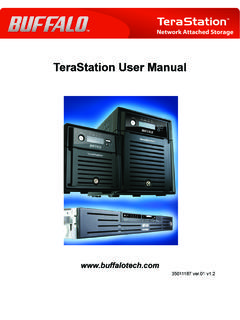
5 Connector kit for various Service cable - IKS0391 .. Selecting the fiber optic cable connections .. Mechanical accessories for **-* .. Mechanical accessories for **-* Drive controllers (with liquid cooling) .. 7-98 Powering up the power sections via charging resistors8-19 Condition at delivery9-110 Identifying the merchandise10-111 Storage and transportation11-112 ,44 the System 1-11 Introducing the SystemInductancelinear motorLAFI nductancelinear motorLARS ynchronous motorMKDS ynchronous 1-1: A digital Drive system with DDSThe modular concept makes it possible to flexibly combine AC servo andmain drives to create one compact Drive package which uses one conjunction with the MDD, MKD and LAR AC motors, the DDS drivecontroller is a rapid-response Drive .
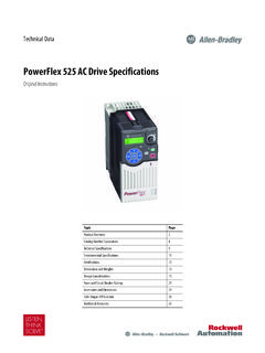
6 These drives are particularly wellsuited for use in machine tool, textile, printing and packaging machineryas well as robotics and handling ,44 the System Individual components of the digital AC servo driveEKdigL-L+X8S1111A3A1A2X1configuredd rive controllerelectricalconnect feedback cableMotorpower cableAC motorplugin moduleFig. 1-2: Individual components of the digital AC Supply units for Drive controllersDDS Drive controllers can be connected to all INDRAMAT supply unitswith a regulated DC 24V : Do not operate the DDS with a TVM supply unit. The DC24V of the TVM is not TVM , TVM supply units or a KDV are used with a DDS drivecontroller, then note the information in Section 8 when powering up thepower section via charging resistors.
7 The application descriptions for eachindividual supply units must also be ,44 guidelines for electrical drives 2-12 Safety guidelines for electrical drivesPrior to using the units, please note the following guidelines on General information The safety instructions in these user guidelines must be observed atall times. Improper use of this equipment and disregarding the war-nings given here can lead to property damage, cause bodily injury or,in extreme cases, lead to is not liable for damages resulting from non-observance ofthe warnings given in these operating instructions. Documentation in the local language must be obtained prior to com-missioning, if the language of the documentation at hand is not un-derstood.
8 Proper transport, correct storage, assembly and installation as well ascareful operation are the prerequisites for optimal and safe operationof this equipment. Qualified personnel:Only appropriately qualified personnel may work on this equipment orwithin its vicinity. Personnel are qualified if they have sufficient know-ledge of the assembly, installation and operation of the product as wellas of all warnings and safety measures in these operating , they should be trained, instructed or qualified to switchelectrical circuits and equipment on and off, to earth and label themaccording to engineering regulations on safety.
9 They should have ade-quate safety equipment and be trained in first aid. Only use spare parts approved by the manufacturer. The safety instructions and regulations for the application must be ob-served. The equipment is designed for installation in machines which are in-tended for commercial use. Start-up is only permitted once it is sure that the machine in which theproducts are installed complies with EC directive 89/392/EWG(machine directives). Operation is only permitted if the national EMC directives for the spe-cific application permit it. Within the EU, EMC directive 89/336 for EMC compliant installation are outlined in the document"EMC for AC drives and controls.
10 Maintaining the national standards is the responsibility of the manu-facturer of the machine or plant. Technical data, connection and installation conditions are outlined inthe respective product documentation and must be Guidelines for protection against contact with electricalpartsIf live parts with voltages exceeding 50 volts are in any way open to con-tact, then this could lead to bodily injury. To operate electrical equipment itis necessary to apply certain parts of it with such dangerous ,44 guidelines for electrical drives 2-2 DANGERHigh electrical voltages!Danger to life and risk of injury! Observe the general construction and safety guideli-nes for work on electrial power installations.