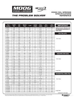
Transcription of DID YOU KNOW? - Federal-Mogul
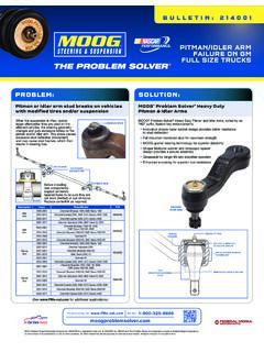
1 After installing MOOG ball joints on Ford Super Duty and Dodge Ram HD straight axle 4x4 and twin I-beam trucks, some customers may encounterpoor steering wheel return (referred to as memory steer ), a tight feel on center on the highway and difficulty when turning the knuckle. This may be the result of ball joint binding due to improper installation. All straight axle and twin I-beam designs have manufacturing variations horizontally between upper and lower taper holes in the knuckle/axle and also variation between mounting locations of the upper and lower ball ball joints have precision metal tolerances (similar to a crankshaft bearing.) When installed properly, they will provide superior service life. Using improper procedures can effect product operation and shorten service life due to the excessive load that these variations can place on ball recommend installing MOOG Problem Solver ball joints:K80026 Upper, K8607T Lower(See MOOG Problem Solver Bulletin 212002 to learn more about these specific ball joints.)
2 Proper installation procedures with MOOG Problem Solver ball joints will ensure a more profitable job, with less comebacks and more satisfied addition, close attention should be paid to the steering gear box, steering damper, and front axle u-joints during the repair procedure. These components, if faulty, can cause symptoms similar to failed ball joints and will result in comebacks and time-consuming the upper ball joint cotter pin and nut. Loosen, but do not remove, the lower ball joint nut. Strike the lower and upper end of the axle to loosen the ball joints. (FIG 3)On Ford applications - Use the Ford service tool to remove the camber adjuster. Note its position. (FIG 4). IT IS IMPERATIVE THAT YOU REMOVE THE BUSHING AND CLEAN THE MATING SURFACES BEFORE the wheel hub, bearing and to the factory service manual for proper safety and repair proceedures.
3 With the axle out, inspect the u-joint. If the u-joint is in poor shape it should be replaced. Failed u-joints can cause noise and binding, and are easily replaced at this point. We recommend replacing with MOOG premium u-joint 374. Remove the tie rod cotter pin and the tie rod end nut. (FIG 1)Using an appropriate tool, disconnect the tie rod end from the wheel knuckle. (FIG 2)Con t next columnCon t next pageDODGERAM 25001998-1994 RAM 2500 PICKUP1999 RAM 35001998-1994 RAM 3500 PICKUP1999 FORDEXCURSION2005-2000F-250 SUPER DUTY2010-1999F-3501997-1992F-350 SUPER DUTY2010-1999F-450 SUPER DUTY2004-1999F-550 SUPER DUTY2004-1999 Vehicles affectedOverviewRemoval Procedure Removal Procedure (con t)Camber Adjuster (if equipped) the lower ball joint nut and the wheel remove the ball joints from the knuckle.
4 It is easier to remove the lower ball joint first. First, remove the snap ring, then use a ball joint press and appropriate receiving cups and remove the upper ball joint from the knuckle, utilizing a ball joint press and appropriate receiving cups and adapters. (FIG 5)AxleSealU-JointKnuckle with Ball JointsTie CupOTC #38354 Upper Ball JointReceiving CupOTC #222305 AdapterOTC #305227 Lower Ball Adjuster FORD APPLICATIONADVICE FOR THE PROFESSIONALDID YOU KNOW? Ball Joint Replacement / Memory Steer IssuesFord Super Duty / Dodge Ram 2550 / 3500 Trucks with Straight AxlesDY K12-101tech parts lookup, visit 2015 Federal-Mogul Motorparts Corporation. NASCAR is a registered trademark of NASCAR, Inc. MOOG and The Problem Solver are trademarks owned by Federal-Mogul Corporation, or one or more of its subsidiaries, in one or more countries.
5 All other trademarks are the property of their respective owners. All rights reserved. Form# DYK12-101 OTC COMPONENTS REQUIRED: Installing Adapter #204508A Installing Cup #38355A Installing Cup #38354 IMPORTANT: THOROUGHLY clean the surface where the new ball joints will seat. DIRTY MATING SURFACES WILL AFFECT BALL JOINT ALIGNMENT AND a ball joint press, press in the new ball joints. It is IMPORTANT that the ball joints are installed properly to prevent misalignment and binding! Be sure to use the correct size adapter. Refer to the following ball joints press in and apply force on the stud end of these applications. It is important that the installation cup be placed on the outer step of the ball joint housing. Pressing in the ball joint with force against the inside lip may push the lip and lower bearing into the stud, causing binding and premature failure.
6 Always press in these ball joints using the outer upper ball joint must be installed before the lower ball Clean the knuckle ball joint mating surfaces Apply a suitable lubricant to the ball joint mating surface and assemble the ball joint into the the ball joint press components as shown in Fig 6. Check the alignment of all components. Tighten the forcing screw until the ball joint is firmly the snap ring on the upper ball Steps 1-3 to install the lower ball joint. Install the snap the knuckle assembly to the vehicle according to the vehicle service manual the UPPER ball joint nut to 94 Nm (69 ft. lbs.) DO NOT USE AN IMPACT WRENCH. An impact wrench can spin the stud at high speed and cause premature failure. (FIG 8)If necessary, tighten the nut until the cotter pin can be installed.
7 Install the cotter the LOWER ball joint nut to 204 Nm (150 ft. lbs.). DO NOT USE AN IMPACT WRENCH. An impact wrench can spin the stud at high speed and cause premature failure. (FIG 7)NOTE: Do not loosen the nut to install the cotter pin. Always tighten to install the cotter the tie-rod end to the wheel knuckle and install the to 115 Nm (85 ft. lbs.) DO NOT USE AN IMPACT WRENCH. An impact wrench can spin the stud at high speed and cause premature failure. If necessary, tighten the nut until the cotter pin can be the repair per the vehicle service manual. Also, a wheel alignment should be performed anytime ball joints are factors to consider:Inspect the steering damper if equipped. Binding from internal rust can cause stiff steering and poor steering wheel is important that the steering gear box is properly adjusted.
8 A steering gear box that is worn or out of adjustment can cause steering looseness, wandering, poor return-to-center, and/or tight and stiff the camber adjuster sleeve (if equipped). Position the wheel knuckle onto the axle and install the nut onto the upper ball joint. Do not tighten the nut at this time. Apply threadlock and sealer to the threads of the lower ball joint and install the nut onto the lower ball joint. Do not tighten the nut at this time. It is important that the following torque procedures be followed: Tighten the LOWER ball joint nut to 59 Nm (44 ft. lbs.) DO NOT USE AN IMPACT WRENCH. An impact wrench can spin the stud at high speed and cause premature failure. (FIG 7)Installation ProceduresInstallation Procedure (con t)Installation Procedure (con t) Cup must sit on outer stepIncorrect fit, not against outer stepINSTALLATION Installing CupOTC #38354 Installing AdapterOTC #204508 AUpper Ball JointInstalling CupOTC #38355 AInstallingAdapterOTC #204508 ALower Ball JointInstalling CupOTC #38354 InstallingAdapterOTC #204508A Upper Ball Joint Installing CupOTC #38355 AInstalling AdapterOTC #204508 ALower Ball BALL JOINT - CORRECTI nstalling Cup OTC #38354 Correct fit, against outer stepK8607 TOuter stepUPPER BALL JOINT - CORRECT Installing Cup OTC #38355AK80026 Correct fit, against outer stepOuter stepFord Super Duty / Dodge Ram 2550/3500 Trucks with Straight Axles SAB A USTED?
9 Continued from previous pageBall Joint Replacement / Memory Steer IssuesFord Super Duty / Dodge Ram 2550 / 3500 Trucks with Straight AxlesDY K12-101tech parts lookup, visit 2015 Federal-Mogul Motorparts Corporation. NASCAR is a registered trademark of NASCAR, Inc. MOOG and The Problem Solver are trademarks owned by Federal-Mogul Corporation, or one or more of its subsidiaries, in one or more countries. All other trademarks are the property of their respective owners. All rights reserved. Form# DYK12-101 Con t next columnCon t next columnDID YOU KNOW? ADVICE FOR THE PROFESSIONAL