Transcription of Digital Modulation in Communications Systems – An …
1 Digital Modulation inCommunications Systems An IntroductionApplication Note 1298 This application note introduces the concepts of Digital Modulation used inmany Communications Systems today. Emphasis is placed on explaining the tradeoffs that are made to optimize efficiencies in system Communications Systems fall into one of three categories: bandwidthefficient, power efficient, or cost efficient. Bandwidth efficiency describesthe ability of a Modulation scheme to accommodate data within a limitedbandwidth. Power efficiency describes the ability of the system to reliablysend information at the lowest practical power level.
2 In most Systems ,there is a high priority on bandwidth efficiency. The parameter to be optimized depends on the demands of the particular system , as can be seen in the following two designers of Digital terrestrial microwave radios, their highest priorityis good bandwidth efficiency with low bit-error-rate. They have plenty ofpower available and are not concerned with power efficiency. They are not especially concerned with receiver cost or complexity because they donot have to build large numbers of the other hand, designers of hand-held cellular phones put a high priority on power efficiency because these phones need to run on a is also a high priority because cellular phones must be low-cost toencourage more users.
3 Accordingly, these Systems sacrifice some bandwidthefficiency to get power and cost efficiency. Every time one of these efficiency parameters (bandwidth, power or cost) is increased, another one decreases, or becomes more complex or does notperform well in a poor environment. Cost is a dominant system radios will always be in demand. In the past, it was possible tomake a radio low-cost by sacrificing power and bandwidth efficiency. Thisis no longer possible. The radio spectrum is very valuable and operatorswho do not use the spectrum efficiently could lose their existing licenses orlose out in the competition for new ones.
4 These are the tradeoffs that mustbe considered in Digital RF Communications design. This application note covers the reasons for the move to Digital Modulation ; how information is modulated onto in-phase (I) and quadrature (Q) signals; different types of Digital Modulation ; filtering techniques to conserve bandwidth; ways of looking at digitally modulated signals; multiplexing techniques used to share the transmission channel; how a Digital transmitter and receiver work; measurements on Digital RF Communications Systems ; an overview table with key specifications for the major Digital Communications Systems ; and a glossary of terms used in Digital RF concepts form the building blocks of any Communications system .
5 If you understand the building blocks, then you will be able to understandhow any Communications system , present or future, works. Digital Modulation ? Trading off simplicity and Industry trends2. Using I/Qmodulation (amplitude and phase control) to convey Transmitting Signal characteristics that can be display - magnitude and phase represented Signal changes or modifications in polar Qin a radio Iand Qin a radio Why use Iand Q?3. Digital Modulation types and relative Bit rate and symbol Spectrum (bandwidth) Symbol Phase Shift Keying (PSK) Frequency Shift Keying (FSK) Minimum Shift Keying (MSK) Quadrature Amplitude Modulation (QAM) Theoretical bandwidth efficiency Spectral efficiency examples in practical Differential Constant amplitude modulation4.
6 Nyquist or raised cosine Transmitter-receiver matched Gaussian bandwidth parameter alpha Filter bandwidth Chebyshev equiripple FIR (finite impulse response) Spectral efficiency versus power consumption5. Different ways of looking at a digitally modulated Power and frequency Constellation Eye Trellis the Multiplexing - Multiplexing - Multiplexing - Multiplexing - Combining multiplexing Penetration versus efficiency7. How Digital transmitters and receivers A Digital Communications A Digital Communications receiver3 Table of contents8.
7 Measurements on Digital RF Communications Power Adjacent Channel Occupied Timing Modulation Understanding Error Vector Magnitude (EVM) Troubleshooting with error vector Magnitude versus phase I/Qphase error versus Error Vector Magnitude versus Error spectrum (EVM versus frequency) of Communications systems11. Glossary of terms 4 Table of contentsThe move to Digital Modulation provides more information capacity,compatibility with Digital data services, higher data security, better quality Communications , and quicker system availability.
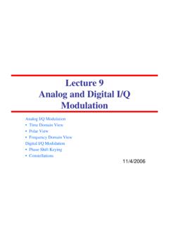
8 Developers ofcommunications Systems face these constraints: available bandwidth permissible power inherent noise level of the system The RF spectrum must be shared, yet every day there are more users forthat spectrum as demand for Communications services increases. Digitalmodulation schemes have greater capacity to convey large amounts ofinformation than analog Modulation schemes. Trading off simplicity and bandwidthThere is a fundamental tradeoff in communication Systems . Simple hardware can be used in transmitters and receivers to communicate information.
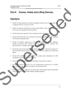
9 However, this uses a lot of spectrum which limits the numberof users. Alternatively, more complex transmitters and receivers can beused to transmit the same information over less bandwidth. The transitionto more and more spectrally efficient transmission techniques requiresmore and more complex hardware. Complex hardware is difficult to design,test, and build. This tradeoff exists whether communication is over air orwire, analog or Why Digital Modulation ?ComplexHardware Less SpectrumSimpleHardware SimpleHardware Fi 1 ComplexHardware More SpectrumFigure Industry trendsOver the past few years a major transition has occurred from simple analogAmplitude Modulation (AM) and Frequency/Phase Modulation (FM/PM) tonew Digital Modulation techniques.
10 Examples of Digital Modulation include QPSK (Quadrature Phase Shift Keying) FSK (Frequency Shift Keying) MSK (Minimum Shift Keying) QAM (Quadrature Amplitude Modulation ) Another layer of complexity in many new Systems is multiplexing. Twoprincipal types of multiplexing (or multiple access ) are TDMA (TimeDivision Multiple Access) and CDMA (Code Division Multiple Access).These are two different ways to add diversity to signals allowing differentsignals to be separated from one , FSK,QPSKV ector Signals AM, FMScalar SignalsTDMA, CDMATime-VariantSignals Required Measurement CapabilitySignal/ system ComplexityFigure in the Transmitting informationTo transmit a signal over the air, there are three main pure carrier is generated at the transmitter.