Transcription of Direct Torque Control of Permanent Magnet Synchronous ...
1 Proceedings of the 6th WSEAS/IASME Int. Conf. on Electric Power Systems, High Voltages, Electric Machines, Tenerife, Spain, December 16-18, 2006 111. Direct Torque Control of Permanent Magnet Synchronous motor (PMSM) an approach by using Space Vector Modulation (SVM). SANDA VICTORINNE PATURCA, MIRCEA COVRIG, LEONARD MELCESCU. Department of Materials, Electrical Machines and Drives University Politechnica of Bucharest 313, Splaiul Independentei, Bucharest ROMANIA. Abstract: - This paper proposes a method of applying the Space Vector Modulation technique for Direct Torque Control (DTC) of a Permanent Magnet Synchronous motor (PMSM) drive. By this method it is preserved the principle of the conventional DTC regarding the decoupled Torque and flux Control , while providing more flexibility for the inverter voltage utilization, in order to compensate the Torque and flux errors in a smoother way than conventional DTC.
2 For this purpose, a reference voltage space vector is calculated every sample time, using a simple algorithm, based on the Torque error and the stator flux angle. Numerical simulations have been made to test the proposed method and results are presented. Key-Words: - Direct Torque Control , Permanent Magnet Synchronous motor , Space Vector Modulation 1 Introduction An effective modality for reducing the Torque ripple Direct Torque Control was introduced by I. without using a high sampling frequency is to Takahashi and T. Noguchi [1] as a new performant calculate a proper reference voltage vector that can Control strategy for induction motor drives fed by produce the desired Torque and flux values, and then Voltage Source Inverters (VSI).
3 Applied to the inverter using SVM. This approach is It was introduced on the market by ABB [4], which known in the literature as DTC-SVM [3], [4]. consider it a viable alternative to Vector Flux In this paper is proposed a simple method for the Oriented Control . calculation of the reference voltage vector, which The main advantages of DTC are the simple Control preserves the conventional DTC principle regarding scheme, a very good Torque dynamic response, as the decoupled Torque and flux Control . well as the fact that it does not need the rotor speed Excepting that inherent complexity is added to the or position to realize the Torque and flux Control (for classical DTC scheme due to the utilisation of SVM, this reason DTC is considerred a sensorless the proposed method for calculating the reference Control strategy).
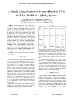
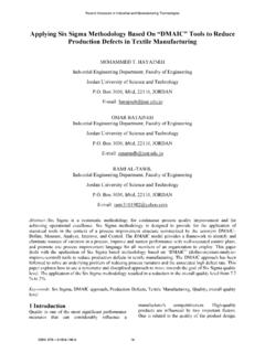
4 Voltage space vector requires little computation These advantages can be fully exploited in those effort. electric drives where not the speed, but only the Numerical simulations have been made for both Torque is to be controlled. For this kind of classical DTC and the proposed DTC-SVM scheme. applications, DTC can be a very attractive option, The results are presented for several motor operating because it is able to provide high dynamic points, to show the improved steady state operation performance at convenient costs. as compared to conventional DTC. However, the classical DTC has some drawbacks, and one of these is the significant Torque and current ripple generated in steady state operation. 2 Direct Torque Control principle Taking into account the large slopes of the resulted The basic model of the classical DTC PMSM motor Torque and the fact that only a single voltage vector scheme is shown in figure 1.
5 It consists of Torque is applied to the inverter in a Control sampling and stator flux estimators, Torque and flux hysteresis period, the classical DTC needs high sampling comparators, a switching table and a voltage source frequencies (above 40 kHz [2]) to obtain a good inverter (VSI). steady state behavior. This requires high The configuration is much simpler than that of the performance controllers, like the DSP, which rises FOC system where frame transformation, rotor the overall cost of the drive. position or speed sensors are required. The basic idea of DTC is to choose the best voltage vector in Proceedings of the 6th WSEAS/IASME Int. Conf. on Electric Power Systems, High Voltages, Electric Machines, Tenerife, Spain, December 16-18, 2006 112.
6 Order to Control both stator flux and electromagnetic Then using equations (3) (6), the magnitude of the Torque of machine simultaneously [1]. stator flux and electromagnetic Torque are calculated At each sample time, the two stator currents iSA and in (7) and (8). iSB and DC-bus voltage UDC are sampled. s = 2 s + 2 s (7). 3. ( ). Two level Hysteresis Te = P s is s is (8). Controller 2. s *. +. 1. Flux Switching where: P is the number of pole pairs 1 S A , S B , SC Voltage reference Table Source Rs is the Stator resistance * + 1 u s (0,1,..,7 ) Inverter The calculated magnitude of stator flux and electric T U DC. Torque . 0. 1. Torque are compared with their reference values in reference Three level their corresponding hysteresis comparators as are Hysteresis shown in figure 1.
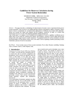
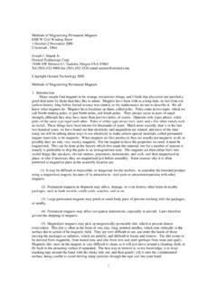
7 S T Controller Finally, the outputs of the comparators and the Flux Sk (1,2,..,6 ) Sector number of sector at which the stator flux space detection PMSM. vector is located are fed to a switching table to select an appropriate inverter voltage vector [5]. Torque and ia ib As shown in figure 2, eight switching combinations Flux calculator can be selected in a two-level voltage source Fig. 1 Block diagram of the conventional DTC inverter, two of which determine zero voltage vectors and the others generate six equally spaced The components of the stator voltage space voltage vectors having the same amplitude. vector in the stationary reference frame are calculated as shown in (1) and (2) [5].. 2 S SC . u s = U DC S A B (1) u 3 (010) u 2 (110).
8 3 2 . 2 S SC S3 S2. u s = U DC B (2). 3 3. where: S A , S B , SC denote the inverter switching states, in which Si = 1 (i = A, B, C ) , if u 4 (011). S4 u 7 (111) u 0 (000) S1 u1 (100). the upper leg switch is on and Si = 0 , if the upper . leg switch is off. The components of the stator current space S5 S6. vector are calculated using equations (3) and (4), u 5 (001) u 6 (101). supposing the motor has the star connection. is = isA (3). i + 2isB. is = sA (4) Fig. 2 The inverter voltage vectors and the stator 3 flux sectors Using the equations (1) (4) and the stator resistance, the components of the stator flux are The selected voltage vector will be applied to the calculated in (5) and (6): AC motor at the end of the sample time.
9 S = (u s Rsis )dt (5). s = (u s Rs is )dt (6) 3 Principle of the proposed method In conventional DTC, a single stator voltage vector The circular trajectory of stator flux is divided into of the inverter standard topology is selected during six symmetrical sections (S1 S6) referred to every Control sampling period, and it is maintained inverter voltage vectors, as shown in figure 2. constant for the whole period. The components of the stator flux are used to By this switching technique, based on hysteresis, determine the sector in which the flux vector are large and small Torque are not differentiated, which located. Proceedings of the 6th WSEAS/IASME Int. Conf. on Electric Power Systems, High Voltages, Electric Machines, Tenerife, Spain, December 16-18, 2006 113.
10 Causes an extra Torque ripple in motor steady state vector in order to achieve a simultaneous and operation. decoupled Control of the stator flux and In the proposed Control scheme, a reference stator electromagnetic Torque . voltage space vector is calculated, in terms of Every Control sample time, one of the inverter magnitude and phase, using the instant value of voltage vector is selected according to the Torque Torque , and the flux angle. and flux errors and the sector in which the actual To determine the normalized magnitude of the flux vector is situated. reference voltage, it was introduced the expression The phase difference, , between the selected (9). voltage vector and the middle of the flux sector, is.