Transcription of Distribution Inside Large Buildings
1 Department of Electrical Engineering Dr. Hussain Al-Mashat 1 Distribution Inside Large BuildingsIn Large Buildings the type of Distribution depends on the building type, dimension, the length of supply cables, and the loads. The Distribution system can be divided in to: The vertical supply system (rising mains). The horizontal supply ( Distribution at each floor level).In most cases a high voltage supply and transformer substation is required. Normally HV switchgear and substation transformers are installed at ground floor ( or basement ). However, often there are appliances with Large power demand installed on the top floors (converters and motors for lifts, air-conditioning equipment and electric kitchens).As it is desirable to brining the high voltage supply as close as possible to the load centers, transformers are installed at the top floor, or if required, additional ones are installed on one of the intermediate such cases transformers with non-inflammable insulation and cooling are arrangement of the rising mains depends on the size and shape of the building and suitable size of shafts for installing cables and bus ducts must be provided in coordination with the building architect.
2 The vertical supply system are implemented in several ways, some of which are :Department of Electrical Engineering Dr. Hussain Al-Mashat 2 Single Rising MainApplications :-Where high supply security is not :-a) The different loads of individual floors are balanced ) Only a small main board is ) Simple in construction and :-Low supply security (a fault in the rising mains effect all floors).Department of Electrical Engineering Dr. Hussain Al-Mashat 3 Department of Electrical Engineering Dr. Hussain Al-Mashat 4 Busway and Busduct Details Department of Electrical Engineering Dr. Hussain Al-Mashat 5 Busway and plug-inarrangement DetailsDepartment of Electrical Engineering Dr. Hussain Al-Mashat 6 Rising Mains DetailsDepartment of Electrical Engineering Dr. Hussain Al-Mashat 7 Grouped SupplyApplications :-High rise building with high load concentration.
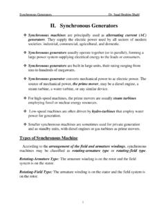
3 Advantages :- Easier mounting. Smaller size for rising :- A fault in any rising mains effect several floors (relatively low security). Loads are balanced only within each group. Larger power Distribution of Electrical Engineering Dr. Hussain Al-Mashat 8 Individual Floor SupplyApplications :-In high rise Buildings were stories are let separately (metering is at central point at ground floor).Advantages :-a) Smaller size of cables can be used (easy installation).b) In the case of a fault in arising main, only one story is :-a) Different loading of the individual floors can not be balanced ) The rising main must be rated for the peak load of each ) Uneconomical Large number of cables and the size of the rising main shaft is quite ) Large low voltage Distribution board with numerous of Electrical Engineering Dr. Hussain Al-Mashat 9 Fifth FloorSecond FloorThird FloorForth FloorFirst FloorGround FloorMDBL&PSMDBL&PL&PL&PXTypical Arrangement of an individualFloor Supply SystemLift SupplyDepartment of Electrical Engineering Dr.
4 Hussain Al-Mashat 10 Ring Main SupplyApplications :-In Large Buildings when relatively higher security is :-a) Higher power supply security ( in the event of a fault, it is possible to switch off the faulty part and leave the majority of the building operational )b) A small low voltage Distribution board is ) The differing loading of individual floor are balanced out ( smaller sizes for rising mains )Department of Electrical Engineering Dr. Hussain Al-Mashat 11 Double Feed SupplyApplications:-In Large Buildings with relatively Large loads at the top floors (lifts, kitchen, air-conditioning).Advantages :-a) Higher power supply ) The differing loading of individual floors are balanced ) Smaller Distribution board practice all supply circuits presented above are used depending on the building type, size, load data, of Electrical & Electronic Eng. Dr. Hussain Al-Mashat!! Constructional Details of 33/11 kV and 11 kVDistribution SubstationsThe power supply to the city of Baghdad is provided basically from two main substations of 400/132 kV (Baghdad East and Baghdad west), which in turn supply many substations of 132/33 kV (or 132/33/11 kV) distributed geographically throughout the city.
5 A schematic diagram showing the structure of this system is given in These 132/33 kV substations in turn provide power supply to a very Large number of 33/11 kV substations as shown in Most of these 33/11 kV substations are equipped with two transformers of MVA each (or 2x16 MVA) as shown in To the 11 kV busbars of these substations (which is divided into two sections) several 11 kV feeders (up to fourteen) are connected using underground cables and/or overhead line circuit branch is served by a draw-out circuit breaker mostly by using one of these types : SF6 Circuit Breaker Vacuum Circuit breaker Minimum-Oil Circuit BreakerThere are about 1150 feeders operating at 11 kV in the city Baghdad alone with a total length of 6845 layout of a typical such substation is shown in Also equipment layout and some constructional details of these substations is shown in small 11 kV transformer size 250 kVA is connected to the 11 Department of Electrical & Electronic Eng.
6 Dr. Hussain Al-Mashat!! kV busbars and used to provide power supply to all substation axillaries. The substation axillaries include providing power supply to emergency lighting, airconditioning, various socket outlets, battery chargers, and all other control and monitoring equipment. Each 11kV feeder provides the supply to Large number of 11 kV Distribution transformers installed using one of the following systems:i. Pole-mounted transformers supplied directly from 11 kV overhead lines through manually operated fused switches. The transformer size in this system is mostly 250 kVA (in few cases in areas with low load density the 100 kVA size is used).ii. Compact type unit substations installed usually at street pavements, in industrial, residential, and commercial areas.. These substations are provided with three compartments: High Voltage CompartmentIt is placed at one side of the substation, and has an independent access through a double-sided door with a specially designed lock.
7 It has the capacity to hold up to three cubicles. Transformer CompartmentThis compartment occupies the middle of the substation and designed to accommodate standard transformers of sizes up to 630kVA (in some cases up to 1000 kVA). The cover of this compartment is removable to enable transformer installation on site. Low Voltage Compartments. The low voltage compartment is placed at the other side of the Department of Electrical & Electronic Eng. Dr. Hussain Al-Mashat!! substation and it is provided with all required protective and control devices. To the low voltage busbars several outgoing kV feedersare installed. Each low voltage feeder provides the power supply to various numbers of consumers. A single line diagram of a typical such substation is shown in compact type unit substations has the following advantages :a) Reduction in civil engineering work (only a small excavation is required)b) Can be easily transported by a truck due to its small sizec) Remarkable reduction in the installation cost (all internal connections are made at the factory)d) Minimum space requirement e) Adaptation to any application using different standard ) Designed for operation outdoors ( weatherproof )g) High operation safety for both the operator and the equipmenth) Reduction in the maintenance cost as compared with open installationsi) Special sandwich construction of walls prevent quick and direct heating of equipment caused by direct sunshine owned substations installed at consumer's premises in building basements or in conventional brick-wall rooms.
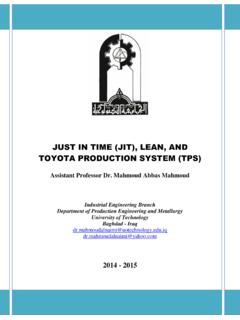
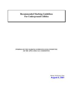
8 Transformer sizes used in this case vary from 100 to 1000 kVA and in accordance with load of Electrical & Electronic Eng. Dr. Hussain Al-Mashat!! B A G H D A D E A S T 4 0 0 / 1 3 2 k VB A G H D A D W E S T 4 0 0 / 1 3 2 k VR a s h d i y aJ a m e e l aT h a w r aM u t h a n n aF a r a b iN e w B a g .Q u s a i b aW a z i r i y aG a z a l iB a g . S o u t hH u r r i y aJ a m i a aY a r m o o kT a g iJ a z a i rD a u r aK a d i m i y aM a a r r yM a n s o o rJ a d i r i y a1 3 2 / 3 3 k V S u b s t a t i o n sS a r r a f i y aM e e d a n1 3 2 / 3 3 k V S u b s t a t i o n s1 3 2 k V1 3 2 k V1 3 2 / 3 3 k V S u b s t a t i o n sF i g . 1 B A G H D A D C I T Y P O W E R S U P P L Y S T R U C T U R EDepartment of Electrical & Electronic Eng. Dr. Hussain Al-Mashat!! x132 kV33 kV11 kVx132 kVx132 kV33 kV11 kVXXXXXX11 kV11 kV11 kV11 kV33/11 kVTransformers33/11 Power Supply Structure to 33/11 kV Substations from Main Satellite Substations Department of Electrical & Electronic Eng.
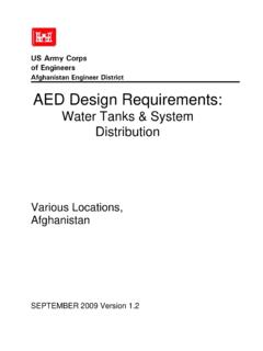
9 Dr. Hussain Al-Mashat!! Single line Diagram of a Typical 33/11 kV SubstationDepartment of Electrical & Electronic Eng. Dr. Hussain Al-Mashat!! Equipment Layout of a Typical 33/11 kV SubstationDepartment of Electrical & Electronic Eng. Dr. Hussain Al-Mashat!! Equipment Layout and Some Constructional Detailsof a Typical 33/11 kV SubstationDepartment of Electrical & Electronic Eng. Dr. Hussain Al-Mashat!! 630500500630100 Spare100500180 kVARPFCI ncoming FeederOutgoing Feeder1000 kVA11 kVTransformer11 kV Load break switches11 kV Load break switch fitted with80 A HRC Fuses1600A TP MCCBAAAVCos 2000A TP&N Copper Busbars1600/5A CT11 Single core cables size 240 mm2each(three cables per phase & two for neutral)MCCBC ircuit Size (A)Two cables size(3x120+70) mm2+ E Single Line Diagram of a Typical 11 kV SubstationTwo cables size(3x185+95) mm2+ E eachDepartment of Electrical & Electronic Eng. Dr. Hussain Al-Mashat!! Equipment Layout of a Typical 11 kV Compact Unit SubstationShowing all Three CompartmentsDepartment of Electrical & Electronic Eng.
10 Dr. Hussain Al-Mashat!! External View of a Privately Owned External View of the 11 kV Ring Main UnitDepartment of Electrical & Electronic Eng. Dr. Hussain Al-Mashat!! Emergency GeneratorsEmergency generators are used to provide critical loads with power supply in the case of mains failure (operating theaters & intensive care units in hospitals, computer Buildings , ).Emergency generators are usually driven by diesel engines, and connected to the load in the following way :a) When the generator is of the same size as the power supply ) When the generator is of a smaller size as compared with the power supply transformerSingle Line Diagram of Main and Emergency Supply Connections for Case a Department of Electrical & Electronic Eng. Dr. Hussain Al-Mashat!! Single Line Diagram of Main and Emergency SupplyConnections for Case bDepartment of Electrical & Electronic Eng. Dr. Hussain Al-Mashat!