Transcription of ELECTRICAL MACHINES II - الجامعة التكنولوجية
1 IInnttrroodduuccttiioonn ttoo AACC MMaacchhiinneess Dr. SSuuaadd IIbbrraahhiimm SShhaahhll 1 ELECTRICAL MACHINES II Lecturer: Dr. SSuuaadd IIbbrraahhiimm SShhaahhll Syllabus I. Introduction to AC Machine II. Synchronous Generators III. Synchronous Motors IV. Three-Phase Induction MACHINES V. Three-Phase Induction Motors VI. Induction Generators VII. Induction Regulators Recommended Textbook : 1) Alternating Current MACHINES Pitman Pub. 2) Langsdorf Theory of AC Machinery McGRAW-HILL Pub. IInnttrroodduuccttiioonn ttoo AACC MMaacchhiinneess Dr. SSuuaadd IIbbrraahhiimm SShhaahhll 2 I. Introduction to AC MACHINES Classification of AC Rotating MACHINES Synchronous MACHINES : Synchronous Generators : A primary source of ELECTRICAL energy.
2 Synchronous Motors : Used as motors as well as power factor compensators (synchronous condensers). Asynchronous (Induction) MACHINES : Induction Motors : Most widely used ELECTRICAL motors in both domestic and industrial applications. Induction Generators : Due to lack of a separate field excitation, these MACHINES are rarely used as generators. Generators convert mechanical energy to electric energy. Energy Conversion Motors convert electric energy to mechanical energy. The construction of motors and generators are similar. Every generator can operate as a motor and vice versa. The energy or power balance is : Generator: Mechanical power = electric power + losses Motor: Electric Power = Mechanical Power + losses. IInnttrroodduuccttiioonn ttoo AACC MMaacchhiinneess Dr.
3 SSuuaadd IIbbrraahhiimm SShhaahhll 3 AC winding design The windings used in rotating ELECTRICAL MACHINES can be classified as Concentrated Windings All the winding turns are wound together in series to form one multi-turn coil All the turns have the same magnetic axis Examples of concentrated winding are field windings for salient-pole synchronous MACHINES MACHINES Primary and secondary windings of a transformer Distributed Windings All the winding turns are arranged in several full-pitch or fractional-pitch coils These coils are then housed in the slots spread around the air-gap periphery to form phase or commutator winding Examples of distributed winding are Stator and rotor of induction MACHINES The armatures of both synchronous and MACHINES armature windings, in general, are classified under two main heads, namely, Closed Windings There is a closed path in the sense that if one starts from any point on the winding and traverses it, one again reaches the starting point from where one had started Used only for MACHINES and commutator MACHINES Open Windings Open windings terminate at suitable number of slip-rings or terminals Used only for MACHINES , like synchronous MACHINES , induction MACHINES , etc Some of the terms common to armature windings are described below: 1.
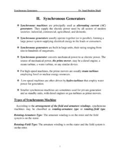
4 Conductor. A length of wire which takes active part in the energy-conversion process is a called a conductor. 2. Turn. One turn consists of two conductors. 3. Coil. One coil may consist of any number of turns. 4. Coil side. One coil with any number of turns has two coil-sides. IInnttrroodduuccttiioonn ttoo AACC MMaacchhiinneess Dr. SSuuaadd IIbbrraahhiimm SShhaahhll 4 The number of conductors (C) in any coil-side is equal to the number of turns (N) in that coil. One-turn coil two-turn coil multi-turn coil 5. Single- layer and double layer windings. Single- layer winding One coil-side occupies the total slot area Used only in small ac MACHINES one coil-side per slot Double- layer winding Slot contains even number (may be 2,4,6 etc.)
5 Of coil-sides in two layers Double-layer winding is more common above about 5kW MACHINES Two coil sides per slot 4-coil-sides per slot Coil- sides Coil- sides Coil -sides Overhang Top layer Bottom layer IInnttrroodduuccttiioonn ttoo AACC MMaacchhiinneess Dr. SSuuaadd IIbbrraahhiimm SShhaahhll 5 The advantages of double-layer winding over single layer winding are as follows: a. Easier to manufacture and lower cost of the coils b. Fractional-slot winding can be used c. Chorded-winding is possible d. Lower-leakage reactance and therefore , better performance of the machine e.
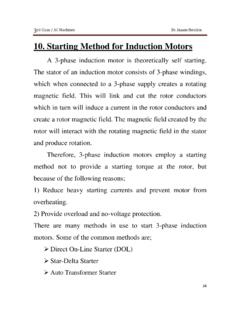
6 Better emf waveform in case of generators 6. Pole pitch. A pole pitch is defined as the peripheral distance between identical points on two adjacent poles. Pole pitch is always equal to 180o7. Coil span or coil-pitch. The distance between the two coil-sides of a coil is called coil-span or coil-pitch. It is usually measured in terms of teeth, slots or ELECTRICAL degrees. ELECTRICAL . 8. Chorded-coil. If the coil-span (or coil-pitch) is equal in case the coil-pitch is to the pole-pitch, then the coil is termed a full-pitch coil. less if there are S slots and P poles, then pole pitch = slots per pole than pole-pitch, then it is called chorded, short-pitch or fractional-pitch coil if coil-pitch = , it results in full-pitch winding in case coil-pitch < , it results in chorded, short-pitched or fractional-pitch Full-pitch coil Short-pitched or chorded coil N S Coil span Pole pitch N S Coil span Pole pitch IInnttrroodduuccttiioonn ttoo AACC MMaacchhiinneess Dr.
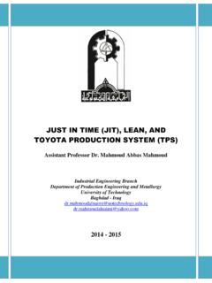
7 SSuuaadd IIbbrraahhiimm SShhaahhll 6 In AC armature windings, the separate coils may be connected in several different manners, but the two most common methods are lap and wave In polyphase windings it is essential that The generated emfs of all the phases are of equal magnitude The waveforms of the phase emfs are identical The frequency of the phase emfs are equal The phase emfs have mutual time-phase displacement of = ELECTRICAL radians. Here m is the number of phases of the machine. Phase spread Where field winding on the rotor to produce 2 poles and the stator carries 12 conductors housed in 12 slots. 3-phase winding - phase spread is 120 o A B C E1 E2 E3 E4 E5 E6 E7 E8 E9 E10 E11 E12 1 2 3 4 5 6 7 8 9 10 11 12 N S IInnttrroodduuccttiioonn ttoo AACC MMaacchhiinneess Dr.
8 SSuuaadd IIbbrraahhiimm SShhaahhll 7 Time phase angle is 120o between EA, EB and E C Maximum emf Em Zero emf induced in conductor 4 (conductor 4 is cutting zero lines of flux) induced in conductor 1 1= 2 R the emf generated in conductor 7 is maximum (conductor 7 is cutting maximum lines of flux from S pole) the polarity of emf in conductor 7 will be opposite to that in conductor 1, = , opposite to E1 similarly the emfs generated in conductors 2, 3, 5, 6 and in conductor 8 to 12 can be represented by phasors E 2, E3 , E5 , E6 and E8 to E12 the slot angle pitch is given by =180 =180 6=30 if = 1+ 2+ 3+ 4 Similarly.
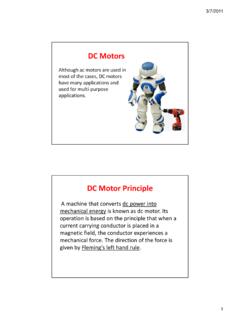
9 = 5+ 6+ 7+ 8 & = 9+ 10+ 11+ 12 the phase belt or phase band may be defined as the group of adjacent slots belonging to one phase under one pole-pair Conductors 1, 2, 3 and 4 constitute first phase group Conductors 5, 6, 7 and 8 constitute second phase group Conductors 9, 10, 11 and 12 constitute third phase group the angle subtended by one phase group is called phase spread, symbol = =4 30 where = = EA EB EC E1 E2 E3 E4 E12 E11 E10 E9 E5 E6 E7 E8 IInnttrroodduuccttiioonn ttoo AACC MMaacchhiinneess Dr. SSuuaadd IIbbrraahhiimm SShhaahhll 8 Sequence of phase-belts (groups) Let 12-conductors can be used to obtain three-phase single layer winding having a phase spread of 60o coil pitch or coil span y = pole pitch = =122=6 ( =60 ) for 12 slots and 2 poles, slot angular pitch =30o for =60 , two adjacent slots must belong to the same phase A B C E1 E2 E3 E4 E5 E6 E7 E8 E9 E10 E11 E12 1 2 3 4 5 6 7 8 9 10 11 12 N S A B C 3-phase winding, phase spread is 60o IInnttrroodduuccttiioonn ttoo AACC MMaacchhiinneess Dr.
10 SSuuaadd IIbbrraahhiimm SShhaahhll 9 (a) (b) Phase spread of 60o(b) Time-phase diagram for the emfs generated in (a) , 12 slots,2 pole winding arrangement A B C E1 E7 E2 -E8 E5 E6 E9 E10 -E11 -E12 -E4 -E3 120o 1 2 3 4 5 6 7 8 9 10 11 12 b b a a c c d d 120o 120o =30o A A A C C B B C C A B B B1 A1 C1 B2 A2 C2 IInnttrroodduuccttiioonn ttoo AACC MMaacchhiinneess Dr. SSuuaadd IIbbrraahhiimm SShhaahhll 10 Double Layer Winding synchronous machine armatures and induction motor stators above a few kW, are wound with double layer windings if the number of slots per pole per phase = is an integer, then the winding is called an integral-slot winding in case the number of slots per pole per phase, q is not an integer, the winding is called fractional-slot winding.