Transcription of Synchronous Machines
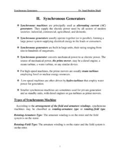
1 Synchronous MachinesConstruction1. Stator - armature (Same as the stator of an InductionMachine)2. Rotor - Field winding ( DC Field)GeneratorIAs a generator, this machine is widely is the machine which is used in all conventional Synchronous generator is called as an it runs only at Synchronous speed, it is not widely usedas a motor but for certain applications like electric , it is used to either produce or absorb reactive StatorIIt is a distributed windings of each phase are distributed over several phase windings are wound 120 (electrical angle) apartin space2. RotorIIt is excited by a DC are two Cylindrical Rotor - used where the turbine speed is Salient Pole Rotor - used where the turbine speed is lowSynchronous machine is a doubly excited can have field winding placed in stator and armature windingin rotor.
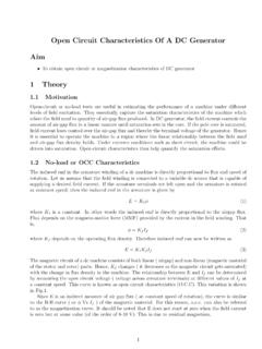
2 This type is called aninverted Synchronous Generator m eB2 2 teB4 ( e)2 ( m) teIn general e=P2 mSource: A. E. Fitzgerald, , Electric Machinery tvIn a 2-pole machine , one revolution makes one cycle of a P-pole machine ,1 revolution/min 160 P2cycle/secNrpm N60 P2cycle/secf=PN120 HzThe flux linkage with stator coilais a=N fcos tWhereNis the number of turns in each pahse and fis the fluxper pole due to excitation currentIf. By Faraday s law, the voltageinduced in phaseaisea= d adt= N fsin tThe rms value in voltage isEa= fE fIThe field winding is excited by the rotor rotates, the field will revolve in the air revolving field induces an emf in the armature windingplaced in the speed of the field (N) is determined by the frequency ofinduced and field due to field winding rotate at the same speedcalled the synchrnous the stator terminals are connected to a load, a threephase armature current flows out of the a three phase balanced current flows in the three phasearmature winding , a revolving mmf is produced whose speed isN=120fPrpmIThe field due to armature current also rotates at thesynchronous speed in the air the net air gap field is the resultant of field due toIfand stator +Fa r= f+ aIThe resultant and component fluxes rotate in the air gap atthe same : OCCE f aIa r Figure.
3 Field diagramEquivalent CircuitSince the operation is balanced, the per phase equivalent circuit ofa Synchronous machine is+ EXarXalRa+ VtwhereXaris the reactance of armature the leakage the armature resistance.+ EXsIaRa+ VtThe Synchronous reactanceXs=Xar+XalThe Synchronous impedanceZs=Ra+ XsE=Vt+Ia(Ra+ Xs)Determination ofXsOpen Circuit Test :RYBNV +EIfField +VfVaryIfand measureE. Repeat tillEreaches its rated Circuit Test :AIaRYBIfField +VfVaryIfand measureIa. Repeat tillIareaches its rated open circuit characteristics is a non linear curve. However, theshort circuit characteristics is a straight line because the flux insidethe machine is low (no saturation).+ EXsIaRaFigure: SC TestE f aIa r Figure: Field diagramOCCSCCVtIaabcdEdaIfEIaIUnsaturate d Synchronous impedance,Zs(unsat)=EdaIaIfRais known,Xs(unsat)can be (unsat)= (Zs(unsat))2 R2aISaturated Synchronous impedance,Zs(sat)=VtIa==Ra+ Xs(sat)IfRais known,Xs(sat)can be (sat)= (Zs(sat))2 R2aSaturated Synchronous reactanceXsis normally used - Phasor DiagramsVtIaRaIaXsEIa Figure: lagging power factor loadVtIaRaIaXsEIa Figure: unity power factor loadVtIaRaIaXsEIa Figure: leading power factor loadIn AlternatorsIEleadsVtby.
4 Is is also the angle between the main field fand theresultant field fleads rby .Let us r a f Figure: Alternator supplies a lagging power factor load - Field diagramSynchronization of AlternatorsRL1 RGridYL2 YGridBL3 BGridIfField +VfThe alternator and the grid must have the same1. Voltage2. Frequency3. Phase Sequence4. PhaseIWhen all the above conditions are satisfied, the three lampswill be dark. It is time to close the it is synchronized, the terminal voltage and frequency ofthe alternator can not be changing the prime mover speed, Real Power (P) can changing the excitation, Reactive Power (Q) and hencepower factor can be CharacteristicIt always works with an infinite bus.+ E XsIaRa+ Vt0 Figure: Per phase equivalent circuitTo find the power delivered by the alternator,S=VtI aS=Vt0 ((E Vt0 )|Zs| ) S=EVt |Zs| V2t |Zs|By taking Real and Imaginary parts,P=EVtcos( )|Zs| V2tcos( )|Zs|Q=EVtsin( )|Zs| V2tsin( )|Zs|If we neglectRa,|Zs|=|Xs|and = 90.
5 P=EVtsin XsQ=EVtcos Xs V2tXsThree phase real and Reactive powerP= 3 EVtsin Xs=Pmaxsin Q= 3(EVtcos Xs V2tXs) PPmaxFigure: Power angle curveV - Curves:+ E XsIa+ Vt0 Figure: Per phase equivalent circuitVtIaXsEIa Figure: Supplying a lagging power factor loadLet us keep the real power delivered constant and change Xs=VtIacos where is the angle difference varied,Efwill vary (linearly if magnetic linearity isassumed). SinceVtis fixed,Esin = constIacos = constVtIa1 XsIaXsIa2 XsE1EE2Ia1 IaIa2 Esin Iacos Figure: Different excitation for a constantPE1sin 1=Esin =E2sin 2Ia1cos 1=Iacos =Ia2cos 21. Over Excitation :Ecos >VtAlternator supplies lagging current and supplies Normal Excitation :Ecos =VtAlternator supplies unity power factor current and supplieszero reactive Under Excitation :Ecos <VtAlternator supplies leading current and draws reactive we plotIaVsIf,P1P2 IfIaP2>P1 Over Excitationlagging pfUnder Excitationleading pfFigure: V-Curves of an AlternatorExample 1 : (Example : Kothari)A 3 , 10 kVA, 400 V, 4-pole, 50 Hz star connected synchronousmachine has Synchronous reactance of 16 and negligibleresistance.
6 The machine is operating as generator on 400 Vbus-bars (assumed infinite).1. Determine the excitation emf (phase) and torque angle whenthe machine is delivering rated kVA at pf While supplying the same real power as in part (1), themachine excitation is raised by 20 %. Find the stator current,power factor, torque angle and reactive power With the field current held constant as in part (1), the power(real) load is increased till the steady state power limit isreached. Calculate the maximum power and kVAR deliveredand also the stator current and power factor. Draw the phasordiagram under these 10 = 8kW (three phase)Ia=8000 3 400 AE =400 30 + 1690 E= V (phase) = E= 496 VEsin =E1sin 1 1= The stator currentIa1=E1 1 Vt0 XsIa1= Apf= laggingQ= 3 VtIasin = kVAR (3-phase)Qcan also be found by the following 3(EVtcos Xs V2tXs)Qis positive which means the machine is supplying VWhen the real power reaches its maximum value, = 90.
7 Pmax=EVtXs= 23116= kW/phasePmax= kW (3-phase)Ia= 2310 1690 = Apf= leadingQ= 3 400 sin( ) = kVAR (3-phase)SinceQis negative, the machine is drawing Synchronous MotorIStator ( armature ) is connected to a three phase AC (field winding ) is connected to a DC three phase induction motors and DC motors, synchronousmotors are us consider a 4-pole Synchronous the three phase armature winding (stator) is suppliedwith a three phase balanced supply, It produces a rotatingmmf in the air gap whose speed is the Synchronous speedNs=120fPFor a 4-pole machine and 50 Hz supply,Ns=1500 the field winding (rotor) is excited by DC, it willproduce a stationary the revolving field rotates, the rotor experiences torqueand is trying rotate in the direction of revolving to inertia of the rotor, rotor filed poles have hardlymoved.
8 By the time stator poles have , the rotor experiences torque in the there is no net torque and the motor will not developany starting : P. C. Sen, Principles of Electric Machines and Power Electronics Methods of Starting1. Use a variable frequency supplyIThe motor is started with a low frequency will make stator field move slowly so that the rotor the frequency is gradually Start as an induction machineISynchronous Machines normally have damper or amortisseurwinding mounted on the not excite the the stator is connected to the three phase ac supply, themachine will start as induction reaching the steady speed (Nr<Ns), excite the rotorwith the DC rotor will get locked to the revolving field and rotate , damper winding will get no induced emf (no relativemotion).
9 Figure: Synchronous machine RotorSource: A. E. Fitzgerald, et. al., Electric Machinery Synchronous Motor - Equivalent Circuit+ EXsIaRa+ VtE=Vt Ia(Ra+ Xs) Synchronous Motor - Phasor DiagramsVtIaRaIaXsEIa Figure: lagging currentVtIaRaIaXsEIa Figure: unity power factor currentVtIaRaIaXsEIa Figure: leading currentIn Syn. MotorsIElagsVtby . is is also the angle between the main field fand theresultant field flags rby .Let us r a fFigure: Syn. Motor draws a lagging current - Field diagramTorque CharacteristicsT=P3 swhere sis the Synchronous speed in rad/sec. s=2 Ns60T=3 EVtsin sXs=Tmaxsin Nm TTmaxFigure: Torque angle curveN(rpm)TNsFigure: Torque speed curvePower Factor Control+ E XsIa+ Vt0 Figure: Per phase equivalent circuitVtIaXsEIa Figure: Drawing a lagging currentLet us keep the real power supplied to the motor constant andchange the Xs=VtIacos ifIfis varied,Efwill vary (linearly if magnetic linearity isassumed).
10 SinceVtis fixed,Esin = constIacos = constVtIa1 XsIaXsIa2 XsE1EE2Ia2 IaIa1 Esin Iacos Figure: Different excitationE1sin 1=Esin =E2sin 2Ia1cos 1=Iacos =Ia2cos 21. Over Excitation :Ecos >VtSyn. motor draws leading current and supplies reactive Normal Excitation :Ecos =VtSyn. motor draws unity power factor current and draws zeroreactive Under Excitation :Ecos <VtSyn. motor draws lagging current and draws reactive we plotIaVsIf,P1P2 IfIaP2>P1 Over Excitationleading pfUnder Excitationlagging pfFigure: V-Curves of a Syn. MotorSynchronous Condenser+ EXs+ VtLet us vary the excitation. SinceVtis fixed,VtEE1Ia1 XsIa1E2Ia2 XsIa2 Figure: Phasor diagram - Generator ConventionVtEE1Ia1 XsIa1E2Ia2 XsIa2 Figure: Phasor diagram - Motor ConventionIAn overexcited unloaded Synchronous machine supplies a purelagging current (draws a pure leading current).