Transcription of Open Circuit Characteristics Of A DC Generator Aim 1 Theory
1 open Circuit Characteristics Of A DC Generator Aim To obtain open Circuit or magnetization Characteristics of DC Generator 1 Theory Motivation open - Circuit or no-load tests are useful in estimating the performance of a machine under different levels of field excitation. They essentially capture the saturation Characteristics of the machine which relate the field mmf to quantity of air-gap flux produced. In DC Generator , the field current controls the amount of air-gap flux in a linear manner until saturation sets in the core.
2 If the pole core is saturated, field current loses control over the air-gap flux and thereby the terminal voltage of the Generator . Hence it is essential to operate the machine in a region where the linear relationship between the field mmf and air-gap flux density holds. Under extreme conditions such as short Circuit , the machine could be driven into saturation. open - Circuit Characteristics thus help quantify the saturation effects. No-load or OCC Characteristics The induced emf in the armature winding of a dc machine is directly proportional to flux and speed of rotation.
3 Let us assume that the field winding is connected to a variable dc source that is capable of supplying a desired field current. If the armature terminals are left open and the armature is rotated at constant speed, then the induced emf in the armature is given by E = K1 (1). where K1 is a constant. In other words the induced emf is directly proportional to the airgap flux. Flux depends on the magneto-motive force (MMF) provided by the current in the field winding . That is, = Kf IF (2). where Kf depends on the operating flux density.
4 Therefore induced emf can now be written as E = K1 Kf If (3). The magnetic Circuit of a dc machine consists of both linear ( airgap) and non-linear (magnetic material of the stator and rotor) parts. Hence, Kf changes ( it decreases as the magnetic Circuit gets saturated). with the change in flux density in the machine. The relationship between E and If can be determined by measuring the open Circuit voltage ( voltage across armature terminals) at different values of If at a constant speed. This curve is known as open Circuit Characteristics ( ).
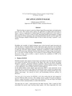
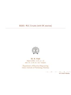
5 This variation is shown in Since E is an indirect measure of air gap flux ( at constant speed of rotation), the curve is similar to the B-H curve ( or Vs If ) of the magnetic material. For this reason, can also be referred to as the magnetization curve. It should be noted that E does not start at zero when the field current is zero but at some value (of the order of 8-10 V). This is due to residual magnetism. 1. Air gap line Air gap mmf Induced emf at no load Er Field Current If ( or field mmf ). Figure 1: Magnetization Characteristics of a DC machine If the magnetization curve is obtained for the rated speed ( 1 ), it can be obtained for any other speed ( 2 ) rather easily.
6 This is due to the fact that, emf induced in the armature windings is proportional to the flux density in the machine air gap and the speed of rotation of field conductors. Hence, similar to (1), we have, E = K10 r (4). E1 1. = = K10 (5). E2 2. 2. E2 = E1 (6). 1. Finally, it should be kept in mind that, when there is no current in the armature winding ( open Circuit condition), the flux produced by the field winding is uniformly distributed over the pole faces. When the machine is loaded, this flux is no longer uniform but distorted depending on the extent of loading.
7 2 Procedure Laboratory Machine Ratings There are three machines mounted on the stand, out of which two of them are dc machines. Note the name plate ratings of these machines and use one of them as a prime mover ( motor) and the other as a dc Generator (You may have to justify your selection ). kW DC machine: Ra = , RF = 415 , Friction & windage loss at 1500 rpm = 53 W. kW DC machine: Ra = , RF = 415 , Friction & windage loss at 1500 rpm = 53 W. Precaution: * Always start the motor (prime mover) by applying a low input voltage (Vin ) to the armature , else the power electronic controller may get damaged due to heavy inrush current (Treat this power electronic controller as a black box.)
8 Input to this controller 2. is single phase AC and the output is DC. The operation of this controller will be explained during the next experiment. The reason for heavy inrush current will also be explained during the next experiment. It should be noted that this experiment is on DC Generator . A prime mover is required for a machine to operate as a Generator . In this experiment DC motor is being used as a prime mover). Also, apply the rated voltage to the field winding of the motor. In case the drive has tripped, bring back the voltage control knob on the power controller feeding armature of the dc motor to zero position' and then press the green' button.
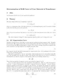
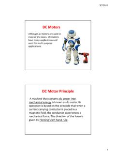
9 Figure 2: Circuit diagram for separately excited DC Generator (for test). A. Connect the Circuit diagram as shown in (you need to connect the field winding across the armature instead of connecting it to a separate supply). B. Slowly increase the input to the prime-mover. Speed of the set will increase. Observe the voltmeter connected across the terminals of the dc Generator . Above a certain speed the voltmeter reading starts increasing (If this does not happen reduce the prime-mover input and switch off the supply.)
10 Interchange the field terminals of the Generator and repeat the same procedure). By controlling the input to the prime mover adjust the speed to the rated speed of the machine. C. Using the knob on the controller feeding the field winding of the Generator , increase the input voltage in steps ( field current will also increase) and for each case determine the open Circuit voltage. Repeat this procedure till the open Circuit voltage is 110% 120% of the rated value. D. Reduce the prime mover input and put off the AC supply to the controller.