Example: bachelor of science
Cyclic Codes - IIT Bombay
Properties of Cyclic Codes (6) Theorem If g(X) is a polynomial of degree n k and is a factor of Xn +1, then g(X) generates an (n;k) cyclic code. Proof. Multiples of g(X) of degree n 1 or less generate a (n;k) linear block code. We need to show that the generated code is cyclic. For a code polynomial v(X) consider the following equation
Tags:
Information
Domain:
Source:
Link to this page:
Documents from same domain

Graphic Symbols for Electrical and Electronics Diagrams
www.ee.iitb.ac.inSymbols for Electrical and Electronics Diagrams of the American National Standards Committee Y32, Graphic Symbols and Designations. There has been close cooperation between the industry and DOD representatives to
DSP APPLICATIONS IN RADAR
www.ee.iitb.ac.inDSP APPLICATIONS IN RADAR S.Bhaktavatsala (02307407) ... Abstract There has been an explosive growth in Digital Signal Processing theory and applications over the years. This seminar report explores the applications of digital signal processing in ... The main task of a radar's signal processor is to make decisions. After a signal has been
Experiment No: 2 Open circuit and short circuit tests on ...
www.ee.iitb.ac.inOpen circuit and short circuit tests on single phase transformer 1 Aim ... of currents and other performance characteristics of a practical transformer. ... the core loss is very small. Hence, the power input on short circuit is dissipated as heat in the winding.
Open Circuit Characteristics Of A DC Generator Aim 1 Theory
www.ee.iitb.ac.inIf the armature terminals are left open and the armature is rotated at constant speed, then the induced emf in the armature is given by E= K 1˚ (1) where K 1 is a constant. In other words the induced emf is directly proportional to the airgap ux. Flux depends on the magneto-motive force (MMF) provided by the current in the eld winding. That is ...
Determination of B-H Curve of Core Material of Transformer ...
www.ee.iitb.ac.inux density in core and A c is the cross-sectional area of the core. So we have E= 4:44B mA cfN (3) The value of induced voltage Eis thus dependent upon B m which can be setup in the core. 2.1 DC Magnetization Curve We know from Biot-Savart’s law that a current carrying conductor produces magnetic eld. \Magnetic
MOSFET Characteristics- Theory and Practice
www.ee.iitb.ac.inOutput DC Characteristics Input Characteristics in Saturation Output Small Signal Characteristics Experiment-Part2 In this part, we investigate the I D −V DS characteristics. The circuit to be used is the same as in Part 1. For a fixed value of V GS, vary V DS to get different values of I D. The expected I D v/s V GS plot is as shown. V DS I D
AN Introduction to VHDL - Overview
www.ee.iitb.ac.inAs a modeling language. For simulation of hardware. For early performance estimation of system architecture. For synthesis of hardware. For fault simulation, test and verification of designs. etc. Dinesh Sharma VHDL
Gaussian Random Variables and Processes
www.ee.iitb.ac.inGaussian Random Variables and Processes Saravanan Vijayakumaran sarva@ee.iitb.ac.in Department of Electrical Engineering Indian Institute of Technology Bombay August 1, 2012 1/33. Gaussian Random Variables. Gaussian Random Variable Definition A continuous random variable with pdf of the form
EE101: RLC Circuits (with DC sources)
www.ee.iitb.ac.inSeries/Parallel RLC circuits R L C i R L C V iR iL R VC V iC L I 0V * A series RLC circuit driven by a constant current source is trivial to analyze. Since the current through each element is known, the voltage can be found in a straightforward manner. V R = i R; V L = L di dt; V C = 1 C Z i …

No-load And Blocked Rotor Test On An Induction …
www.ee.iitb.ac.inFor wound-rotor construction, one can assume that X s1 ˇX r1 resulting in X s1 = X r1 = 0:5 X br. However, for squirrel cage induction machines, the distribution of X br can be obtained from a look-up table indicating empirical distribution of leakage reactance for the machine type. If X s1 is known, from the no-load test data, we have, X m ...
Related documents
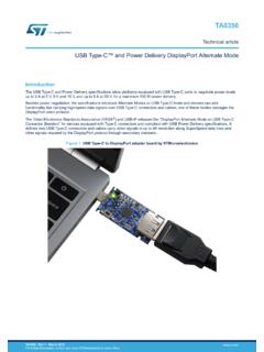
USB Type-C and Power Delivery DisplayPort Alternate Mode
www.st.comFeb 10, 2018 · Whenever a source or a sink receives a message, they validate the message with a cyclic redundancy check (CRC) and send a GoodCRC confirmation message if the check passes. If the check does not pass, the message
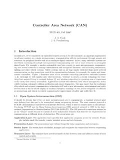
Controller Area Network (CAN) - Electrical Engineering and ...
www.eecs.umich.eduCyclic Redundancy Check (CRC) 15 CRC Delimiter 1 Must be recessive Acknowledge (ACK) 1 Transmitter sends recessive; receiver asserts dominant ACK Delimiter 1 Must be recessive End of Frame (EOF) 7 Must be recessive 1.2.2 The CAN Data Frame The CAN data frame is composed of seven fields: Start of frame (SOF), arbitration, control, data, cyclical
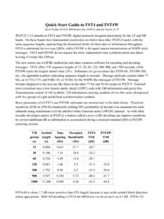
Quick-Start Guide to FST4 and FST4W - Princeton University
physics.princeton.edu50-bit payload. A 24-bit cyclic redundancy check (CRC) is calculated from and appended to each 50-bit information packet to create a 74-bit message-plus-CRC word. The CRC algorithm uses the polynomial 0x100065b (hexadecimal) and an initial value of zero.

PIC32MX5XX/6XX/7XX Family Data Sheet - Microchip …
ww1.microchip.com• 32-bit Programmable Cyclic Redundancy Check (CRC) • Six additional channels dedicated to USB, Ethernet and CAN modules Input/Output • 15 mA or 10 mA source/sink for standard VOH/VOL and up to 22 mA for non-standard VOH1 • 5V-tolerant pins • Selectable open drain and pull-ups • External interrupts Class B Support
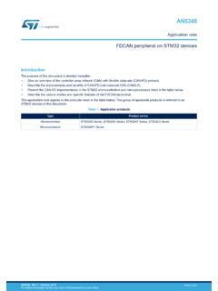
FDCAN peripheral on STM32 devices - Application note
www.st.comCRC = Cyclic redundancy check EOF = End of frame IFS = Interframe space DLC = Data length code r0, r1: 1st and 2nd reserved bits The first arbitration phase is a message that contains: • a start of frame (SOF) • an ID number and other bits, that indicate the purpose of the message (supplying or requesting data), and

Tutorial: Checksum and CRC Data Integrity Techniques for ...
users.ece.cmu.edu3 Checksums and CRCs Protect Data Integrity • Compute check sequence when data is transmitted or stored – Data Word: the data you want to protect (can be any size; often Mbytes) – Check Sequence: the result of the CRC or checksum calculation – Code Word = Data Word with Check Sequence Appended • To check data integrity: – Retrieve or receive Code Word

BOSCH - University of California, Riverside
esd.cs.ucr.eduApr 05, 1995 · BOSCH CAN Specification Version 2.0 1991, Robert Bosch GmbH, Postfach 50, D-7000 Stuttgart 1 Thi d t t d ith F M k 4 0 4

Enhanced Serial Peripheral Interface (eSPI)
www.intel.comIntroduction 327432-004 9 2 Introduction This base specification describes the architecture details of the Enhanced Serial Peripheral Interface (eSPI) …