Transcription of DSP APPLICATIONS IN RADAR
1 Page 1 of 11 M. Tech Credit Seminar Report, Electronic Systems Group, EE Dept, IIT Bombay, Nov2002 DSP APPLICATIONS IN RADAR (02307407) Supervisor: Dr Vikram M. Gadre, Associate Professor Abstract There has been an explosive growth in digital signal processing theory and APPLICATIONS over the years. This seminar report explores the APPLICATIONS of digital signal processing in RADAR . A survey on APPLICATIONS in digital signal processing in RADAR from a wide variety of areas is carried out. A review is done on basic approaching models and techniques of signal processing for different parameters and extracting information from the received signal . The various techniques adopted at different stages of RADAR to obtain the target s signature, is also briefed. Introduction Flexibility and versatility of digital techniques grew in the front-end signal processing and with the advent of integrated digital circuitry, high speed signal processors were developed and realized.
2 RADAR continued to grow in the recent years by keeping the future developments in mind and with better digital capability. Significant contributions in DSP in RADAR have been in MTI processing , Automatic Detection and extraction of signal , Image reconstruction, etc. A case study on RADAR Synthetic Vision System for Adverse Weather Aircraft landing is discussed. In this report an effort is made to identify the contribution of DSP in the advancement of Radars. I. Modern RADAR RADAR transmits radio signals at distant objects and analyzes the reflections. Data gathered can include the position and movement of the object, also RADAR can identify the object through its "signature" - the distinct reflection it generates. There are many forms of RADAR - such as continuous, CW, Doppler, ground penetrating or synthetic aperture; and they're used in many APPLICATIONS , from air traffic control to weather prediction.
3 In the modern RADAR systems digital signal processing (DSP) is used extensively. At the transmitter end, it generates and shapes the transmission pulses, controls the antenna beam pattern while at the receiver, DSP performs many complex tasks, including STAP (space time adaptive processing ) - the removal of clutter, and beamforming (electronic guidance of direction). The front end of the receiver for RADAR is still often analog due the high frequencies involved. With fast ADC convertors- often multiple channel, complex IF signals are digitized. However, digital technology is coming closer to the antenna. We may also require fast digital interfaces to detect antenna position, or control other hardware. The main task of a RADAR 's signal processor is to make decisions. After a signal has been transmitted, the receiver starts receiving return signals, with those originating from near Page 2 of 11 objects arriving first because time of arrival translates into target range.
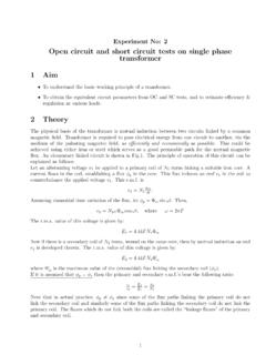
4 The signal processor places a raster of range bins over the whole period of time, and now it has to make a decision for each of the range bins as to whether it contains an object or not. This decision-making is severely hampered by noise. Atmospheric noise enters into the system through the antenna, and all the electronics in the RADAR 's signal path produces noise too. A. Major blocks of modern RADAR system The major components of modern RADAR are the antenna, the tracking computer and the signal generator. The tracking computer in the modern RADAR does all the functions. By scheduling the appropriate antenna positions and transmitted signals as a function of time, keeps track of targets and running the display system. Fig 1. Block Diagram of a Modern RADAR system adopted from [6] Even if atmospheric attenuation can be neglected, the return from a distant object is incredibly weak.
5 Target returns often are no stronger than twice the average noise level, sometimes even buried under it. It is quite difficult to define a threshold for the decision whether a given peak is noise or a real target. If the threshold is too high then existing targets are suppressed, that is, the probability of detection (PD) will drop. If the threshold is too low then noise peaks will be reported as targets, that is, the probability of false alarms (PFA) will rise. A common compromise is to have some 90% probability of detection and a false alarm rate of 10-6. It maintains a given PFA known as CFAR, for Constant False Alarm Rate. Rather than keeping the threshold at a fixed point, CFAR circuitry inspects one range bin after the other and compares the signal level found there with the signal levels found in its neighboring bins.
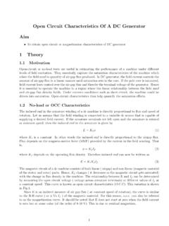
6 If the noise level is rather high in all of these (eg, because of precipitation) then the CFAR circuit will raise the threshold accordingly. Antenna System Txr Threshold Detection Reciever A/D Convertor signal Generator Matched Filters Tracking & Scheduling Control Clutter mapping, discrimination,Range marking, Interpolation, Monopulse computations Display processing Control paths Tracking Computer Processed RADAR Returns Page 3 of 11 Further tasks of the signal processor are: Combining information: Secondary surveillance radars like those located on airports can ask an aircraft's transponder for information like height, flight number or fuel state. Pilots may also issue a distress signal via the transponder. The ground RADAR 's signal processor combines this data with its own measurements of range and angular direction and plots them all together on the appropriate spot on the scope.
7 Forming tracks: By correlating the data sets which were obtained in successive scan cycles, the RADAR can calculate a flight vector which indicates an aircraft's speed and expected position for the next scan period. Airport radars are capable of tracking hundreds of targets simultaneously, and flight safety depends heavily on their reliability. Military tracking radars use this information for gun laying or guiding missiles into some calculated collision point. Resolving ambiguities in range or Doppler measurements: Depending on the RADAR 's pulse repetition frequency (PRF), the readings for range, Doppler or even both are ambiguous. The signal processor is aware of this and selects a different PRF when the object in question is measured again. With a suitable set of PRFs, ambiguities can be eliminated and the true target position can be determined.
8 Ground Clutter Mapping: Clutter is the collective term for all unwanted blips on a RADAR screen. Ground clutter originates from buildings, cars, mountains etc, and a clutter map serves to raise the decision threshold in areas where known clutter sources are located. Time and power management: Within a window of some 60 x40 , phased array radars can instantly switch their beam position to any position in azimuth and elevation. When the RADAR is tasked with surveying its sector and tracking dozens of targets, there's a danger of either neglecting part of the search sector or losing a target if the corresponding track record isn't updated in time. Time management serves to maintain a priority queue of all the tasks and to produce a schedule for the beam steering device.
9 Power management is necessary if the transmitter circuitry runs the danger of overheating. If there's no backup hardware then the only way of continuing regular operation is to use less power when less power is required, say, for track confirmation. Countering interference: Interference can be a) natural, or b) man-made. Natural interference can be heavy rain or hail storms, but also varied propagation conditions. Man-made interference, if created on purpose, is also called jamming and is one of the means of electronic countermeasures. B. Detection of Signals Detection is the process by which the presence of the target is sensed in the presence of competing indications which arise from background echoes (clutter), atmospheric noise, or noise generated in the RADAR receiver.
10 The noise power present at the output of the RADAR receiver can be minimized by using filter, whose frequency response function maximizes the output peak- signal to mean-noise (power) ratio is called matched filter. we shall discuss the application of digital filtering to matched filters. C. Fast Convolution Filter implementation[5] a. Dual pipeline FFT matched Filter In this system, FFTs are pipelined and both the forward and reverse radix-r FFTs are implemented in hardware. Initial recording of the data is done using input buffer (IB) memory and it takes N/r clock pulses to read N data points and r input rails. The amount of time N/r is called as one epoch. It requires three epochs for the first data to be completely Page 4 of 11 filtered, and is delivered by one epoch thereafter.