Transcription of DISTRIBUTION TRANSFORMERS MODELING WITH …
1 DISTRIBUTION TRANSFORMERS MODELING WITH ANGULARDISPLACEMENT - ACTUAL VALUES AND PER UNIT ANALYSISD ario E. Rodas R. Padilha-Feltrin F. Ochoa Universidad Tecnol gica de Pereira (UTP) - Pereira, ColombiaPhone: +57 63212044 UNESP - Campus de Ilha SolteiraAv. Brasil 56, Ilha Solteira - SP, BrazilPhone: +55 18 3743 1169 University of EdinburghEdinburgh EH9 3JL, UKPhone: +44 131 6505575 ABSTRACTIn this work a detailed MODELING of three-phase distributiontransformersaimedatcomplemen tingwell-knownapproaches is , incidence of angulardisplacement and tapping is taken into account in theproposed models, considering both actual values and perunit.
2 The analysis is based on minimal data requirement:solely short-circuit admittance is needed since three-phasetransformers are treated as non-magnetically-coupledsingle-phase TRANSFORMERS . In order to support the proposedmethodology, results obtained through laboratory tests : Transformer MODELING , angular displacement , DISTRIBUTION submetido em 04/05/20061a. Revis o em 22/08/20062a. Revis o em 15/05/2007 Aceito sob recomenda o do Editor AssociadoProf. Denis Vinicius Coury1 NOMENCLATUREVx:Voltage corresponding to windingx,x [1,6].Va, Vb, Vc:Voltages corresponding to primary-side phasesa, , VB, VC:Voltages corresponding to secondary-sidephasesA, , Z2:Impedances corresponding to windings 1 and 2, :Mutual impedance between windings 1 and , I2:Currents corresponding to windings 1 and 2, , n2:Turns corresponding to windings 1 and 2, t:Short-circuit admittance referred to the primary :Transformation ratio.
3 [Y p]:Primitive admittance Revista Controle & Automa , Novembro e Dezembro 2007Sn:Base , Vn2:Base voltages corresponding to windings 1 and 2, :Base , X:Resistance and reactance, respectively. , :Tap variations at the primary and secondary sidesrespect to their nominal values, respectively.[Y bus]:Admittance matrix.[Ypp],[Yps],[Ysp],[Yss]:Submatric es of matrix[Y bus].[N]:Connection matrix.[Npp],[Nss]:Submatrices of matrix[N]. INTRODUCTIONIt is well known that TRANSFORMERS are fundamental elementsof power systems, requiring proper models so accurateanalyses of the network can be performed.
4 In transmissionsystem, transformer MODELING is single-phase based sinceits operation is considered to be balanced. On the otherhand, given the inherent unbalance nature of distributionsystems, a detailed MODELING of DISTRIBUTION transformersrequires a three-phase approach taking into accounta b ccomponents, including neutral and ground effects. Thus,three-phase transformer MODELING has been the focus ofseveral researches (Chenet alli, 1991; Chen and Chang,1992; Chenet alli, 1996; Chen and Chang, 1996; Baran andStaton, 1997; Kerstinget alli, 1999; Kersting, 2002; Dugan,2003; Wanget alli, 2004; Xiaoet alli, 2006).
5 Nonetheless,models found in the literature still lack of details regardingsome connections, angular displacement and on the power flow algoithm adopted for thedistribution network analysis, transformer models may leadto convergence problems. Consequently, some proposals aregiven in the literature in order to minimize this effect (Chenand Chang, 1996; Baran and Staton, 1997; Kerstinget alli,1999; Wanget alli, 2004; Xiaoet alli, 2006). Evaluation ofthe impacts that certain transformer models present on thepower flow analysis is out of the scope of this transformer models presented in 1991 by Chenetallihave been widely used by researchers and commercialsoftware, their applicability outside the US is limited sincethe angular displacement is commonly restricted to two clockhours.
6 1 and 11, depending on whether it is a step-up or step-down objective of this paper is to improve and to makeas general as possible widely-accepted transformer models,considering angular displacement as well as tapping in bothprimary and secondary windings. It is also demonstratedthat DISTRIBUTION TRANSFORMERS can be modeled as powertransformers when analyzing variable transformer models allow including angulardisplacement, which is a basic tool for generalizingtransformer models to other different clock hours or evenvector discussion about circuit and matrixmodeling considering the variables in actual values and in perunit is also included.
7 Models in actual values (Siemens) arefully described since they allow obtaining directly all majorparameters involved in the transformer MODELING , leading toa better understanding of the per unit analysis. Moreover,in order to validate the proposed methodology, results fromlaboratory tests are speaking, there two ways to model distributiontransformer. One requires a large quantity of data (Gormanand Grainger, 1992), which is often difficult to obtain. Theother way considers the use of minimal information (onlythe short-circuit admittance is needed) whereas the core ismodeled as a load (Dugan, 2003; Chenet alli, 1991).
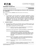
8 Themodeling presented in this work is classified in the , this proposal allows the MODELING ofall kinds of winding connections given by the AmericanNational Standards Institute (ANSI) and the InternationalElectrotechnical Commission (IEC).The structure of this paper is as follows: section 3 presentsthe fundamental concepts for single-phase TRANSFORMERS ,whereas in section 4 the incidence of taps on single-phasetransformers is addressed. DISTRIBUTION transformer analysisis presented in section 5. Finally, in section 6 transformerbank MODELING is addressed taking into account actual valuesand per unit, as well as angular displacement and SINGLE-PHASETRANSFORMERFUNDAMENTAL CONCEPTSA single-phase transformer model based on matrices and,initially, considering its nominal values (winding 1 withn1turns and winding 2 withn2turns), as presented in figure 1,is given by: V1V2 = Z1 ZmZmZ2 I1I2 (1)These values are winding based, primitive impedance Controle & Automa , Novembro e Dezembro 2007 491 Figure 1.
9 Single-phase transformer without t=Z2Z1Z2 Z2m(2)Equations (1) and (2) could be either based on actual valuesor Regarding the case of actual values in equation (2),Y tis the short-circuit admittance referred to the primary. Then,the primitive admittance matrix is:[Y p] = Y t aY t aY t a2Y t (3)wherea= [Y p]in is obtained by dividing each term ofequation (3), whose units are Siemens, by its correspondingbase values:Yp base=SnV2n1, Yps base=SnVn1Vn2andYs base= : primary ands: , substitutinga=Vn1Vn2, the primitive admittance[Y p] is obtained:[Y p]pu= ypu ypu ypuypu (4)4 GENERALMATHEMATICALMODELFORASINGLE-PHASE TRANSFORMERWITHVARIABLETAPSWhen taps vary, fundamentally two parameters experiencealterations:a)The voltage at the secondary side of the transformer dueto the new transformation ratio, and.
10 B)The transformer short-circuit impedance since theinductive reactance is a function of the squared numberof turns. When modifying the number of turns, theresistance is also nominal values are considered (taps at their nominalpositions in both primary and secondary sides), short-circuittests are performed in order to obtain the transformer snominal admittance:Y Off-nominalTapsincidenceonTransformer s ImpedanceIn power TRANSFORMERS , where the resistance can be neglected(Z X), tap variations modify the impedances accordingto the new number of turns and quadratically since theinductance is a function of the squared number of and be the tap variations at the primary andsecondary sides respect to their nominal values, , when taps are altered, the new transformer ratio is:anew=a.